Device for equipping an expansion joint between concrete slabs

a technology of expansion joints and concrete, applied in the field of construction, can solve the problems of reducing the strength of the slab near the joint, one half of the slab, and requiring a great deal of labour

Inactive Publication Date: 2008-09-18
PLAKABETON
View PDF6 Cites 19 Cited by
  • Summary
  • Abstract
  • Description
  • Claims
  • Application Information

AI Technical Summary

Benefits of technology

[0014]According to a first embodiment, the invention is related to a device composed of two profiles which fit together, one in the other, by discontinuous bracket-shaped projections in order to ensure continuity in a slab in line with a joint while still permitting movements in the horizontal plane and protecting the slab edges, but opposing any lift and differential transverse movements.

Problems solved by technology

The problems associated with joints between slabs are well known in the construction field.
This type of profile has the great drawback of reducing the strength of the slab near the joint, since it cuts the joint continuously at mid-height: only one half of the slab withstands heavy loads.
In addition, to produce angled joint junctions is particularly tricky and requires a great deal of labour.
However, this device, although already more effective, does not provide a solution to the lift of the slab edges since it may be likened to an articulation.
This solution is advantageous from a strength standpoint, but it is very expensive to manufacture because of the amount of steel used, and it has several installation difficulties since the form of the foundation must be set perfectly level before the device is put into place.

Method used


Image

  • Device for equipping an expansion joint between concrete slabs
  • Device for equipping an expansion joint between concrete slabs
  • Device for equipping an expansion joint between concrete slabs

Examples


first embodiment

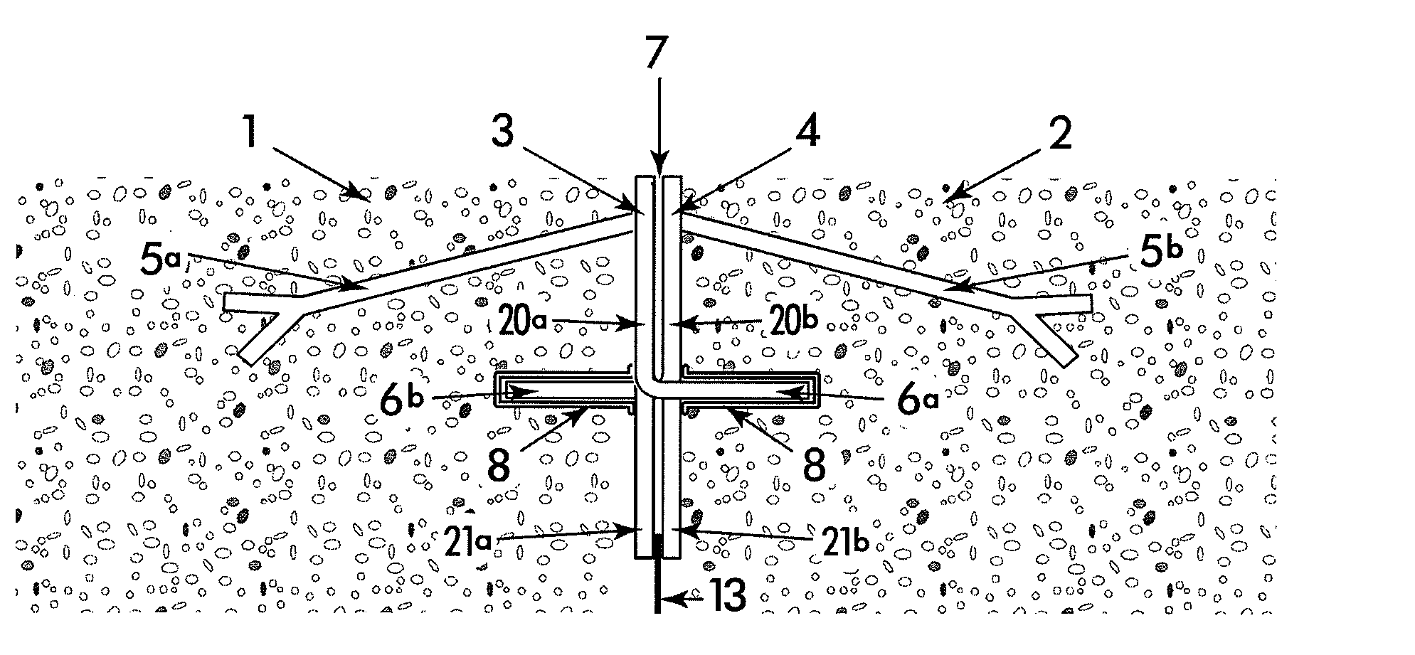
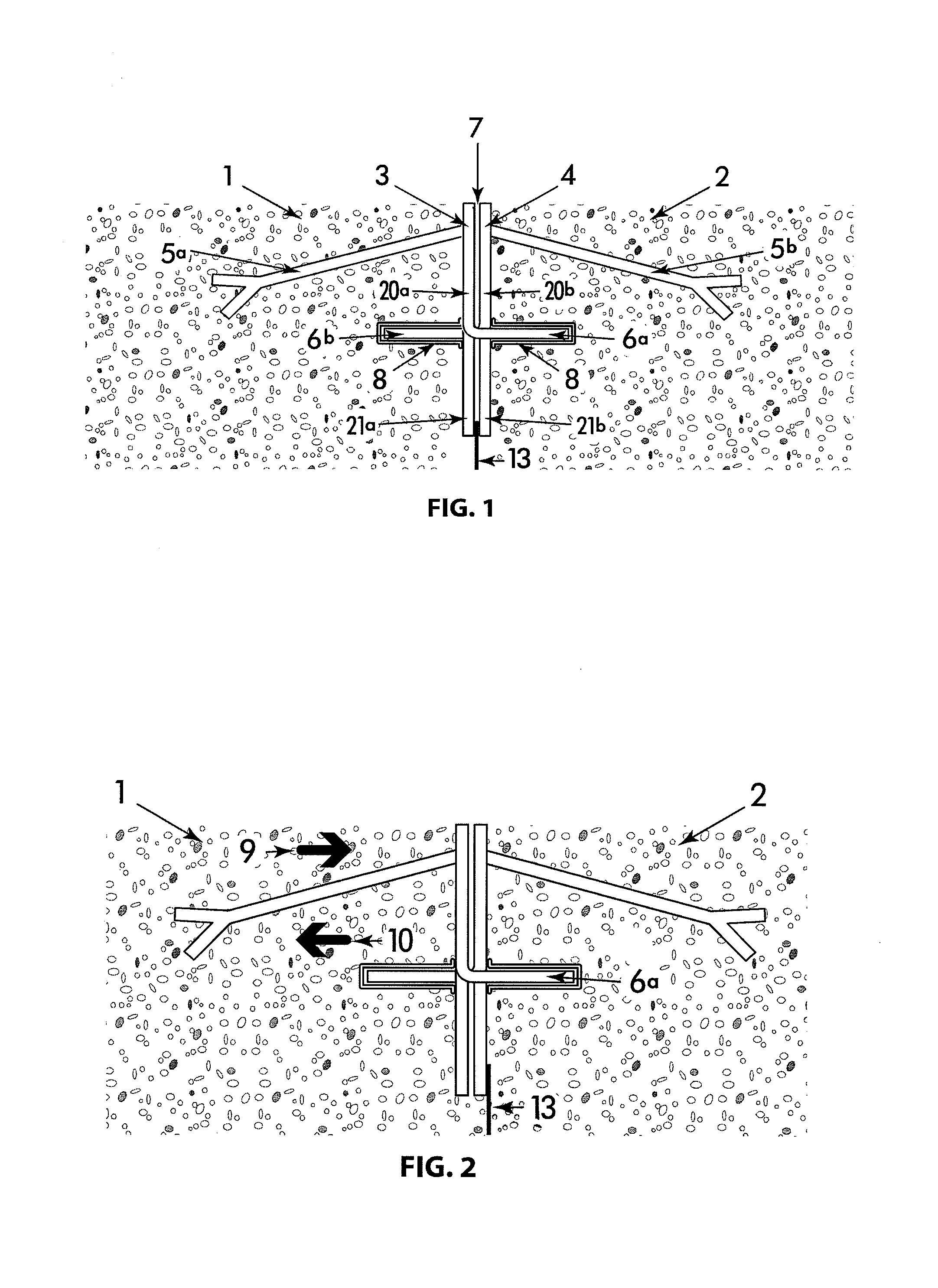
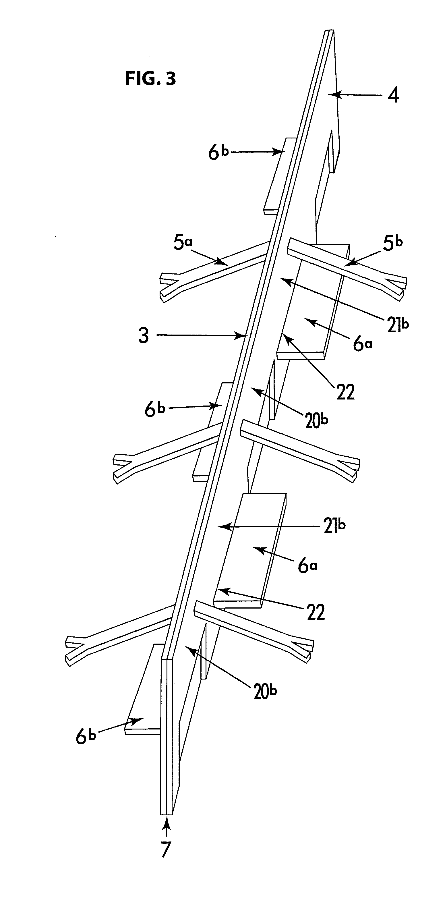
[0025]FIG. 1 gives an example of the device according to the Placed in the joint separating two slabs 1 and 2 is a device composed of two profiles 3 and 4, preferably made of metal, each placed vertically and anchored in the slab on one side of the joint by means of anchoring dowels 5a, 5b. Certain parts 6a, 6b of the profiles 3 and 4 have been bent up at discrete places in order to pass through the joint 7 and the other profile in order to extend into the other slab. The device is such that the bent-up projections 6a,6b are alternately in one slab then in the other slab on each side of the joint 7. A sheath 8 placed over this bent-up projection allows the latter to move in all directions in the plane of the slab, but independently of the latter. The sheath 8 is necessary for a good operation of the device, but it is not necessarily a part of the device as such. It can be attached in a temporary way to the profiles, or simply placed over the projections before the device is install...

second embodiment

[0033]FIG. 5 gives an example of the device according to the invention. Placed in the joint separating two slabs 1 and 2 is a device composed of a profile 30 and another, smaller, profile 31, both preferably being made of metal, each placed vertically and anchored in the slab on one side of the joint 7 by means of anchoring dowels 32a,32b. The lower part of the first profile 30 is divided into segments which are bent up alternately, to form bent-up projections 33a,33b in the two slabs 1 and 2. A sheath 35 is placed over the projections passing through the joint 7, thereby allowing said projections to move in all directions in the plane of the slab, but independently of the latter. A thinner piece 36 is placed beneath the device in order to close off the joint. The parts 35 and 36 are not a part of the device as such. They are necessary for a good operation of the device. The sheaths 35 may be attached in a temporary way to the profile, or simply placed over the projections before th...


PUM


Abstract

A device equips an expansion joint between slabs in building constructions, in particular concrete slabs. According to a first embodiment, the device is made up of two profiles (3,4) that fit together in such a way that the elements passing through the joint between the slabs are discontinuous and have a bracket shape anchored by plate dowel anchors. According to a second embodiment, the device has a single profile, the lower part of which is bent alternately in one slab part and the other on each side of the joint.

Description

FIELD OF THE INVENTION[0001]The present invention is related to the construction field, in particular to the production of concrete slabs for example used as industrial floors, and to the devices that equip the joints between parts of slabs.[0002]In this description, the word “joint” is used exclusively to denote the zone or space between two adjacent slabs while, in the area of construction, this term is generally used to refer to the device itself which occupies such a zone.State of the Art[0003]The problems associated with joints between slabs are well known in the construction field. The device that equips them must be able to fulfil one or advantageously several functions:[0004]absorb dimensional variations due to shrinkage and temperature differences;[0005]support heavy loads, leaving the slabs level;[0006]protect the slab edges in the upper part;[0007]reduce the lift of the slab edges following differential shrinkage in the thickness.[0008]Originally, joints were equipped wit...

Claims


Application Information

Patent Timeline
Patent Type & Authority Applications(United States)
IPC IPC(8): E04B1/68
CPCE01C11/14
Inventor MICHIELS, PIERRE
Owner PLAKABETON
Why Eureka
Try Eureka