Distributed data center system protocol for continuity of service in the event of disaster failures

a data center and disaster failure technology, applied in data processing applications, redundant hardware error correction, instruments, etc., can solve the problems of not providing any means to orchestrate the propagation of updates from multiple logs, not being able to build a highly available system, and not being able to build a system

Inactive Publication Date: 2005-08-09
HEWLETT-PACKARD ENTERPRISE DEV LP +1
View PDF10 Cites 27 Cited by
  • Summary
  • Abstract
  • Description
  • Claims
  • Application Information

AI Technical Summary

Benefits of technology

[0010]The present invention provides a protocol that guarantees continuous database service operation which (a) ensures continuity of service in the event of data center disasters and database crashes, (b) provides strong and well-defined consistency guarantees, (c) allows commercial, off-the-shelf, databases from different vendors to be used together in the system, and (d) tolerates unreliable failure detector mechanisms within data centers.

Problems solved by technology

For distributed data center computer systems, disasters can be caused by the environment (e.g., floods, earthquakes, fires), and also a coincidence of events within the computer system itself (e.g., operator errors, simultaneous crash of critical components due to software faults).
These systems do not provide any means to orchestrate the propagation of updates from multiple logs.
However, parallel databases are inherently homogeneous systems: it is not currently possible to build a highly available system by combining standard databases from different vendors.
In the past, it has not been possible to build a system which: (a) ensures continuity of service in the event of data center disasters and database crashes, (b) provides strong and well-defined consistency guarantees, (c) allows commercial, off-the-shelf, databases from different vendors to be used together in the system, and (d) tolerates unreliable failure detector mechanisms within data centers.
A solution to these problems has been long sought but has long eluded those skilled in the art.

Method used


Image

  • Distributed data center system protocol for continuity of service in the event of disaster failures
  • Distributed data center system protocol for continuity of service in the event of disaster failures
  • Distributed data center system protocol for continuity of service in the event of disaster failures

Examples


Embodiment Construction

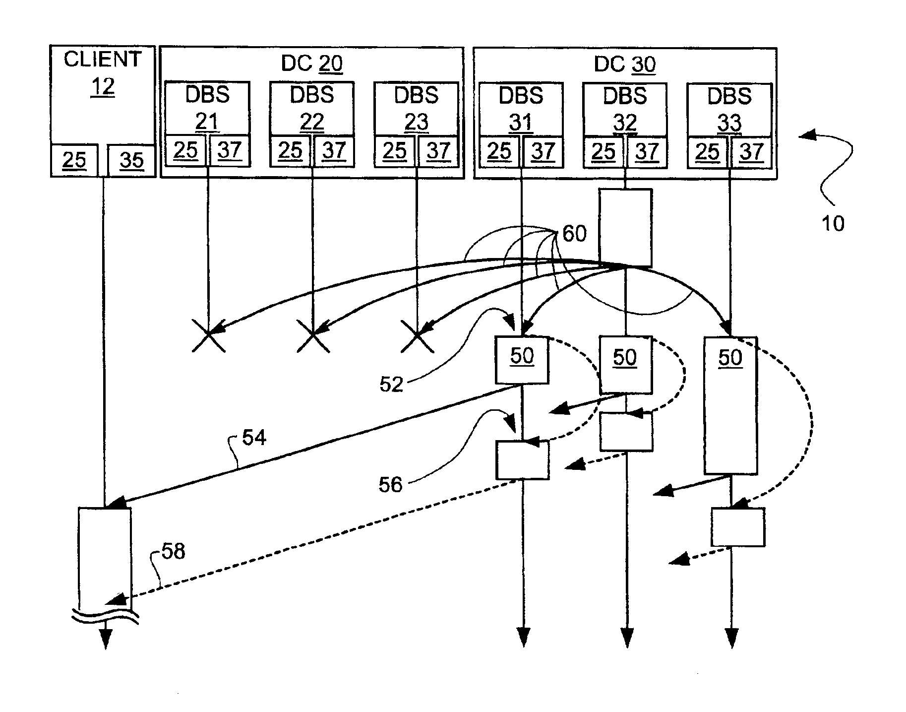
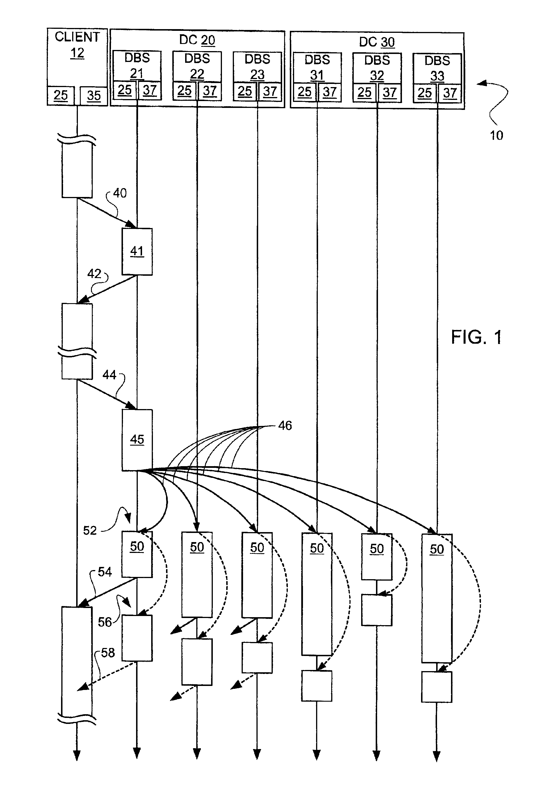
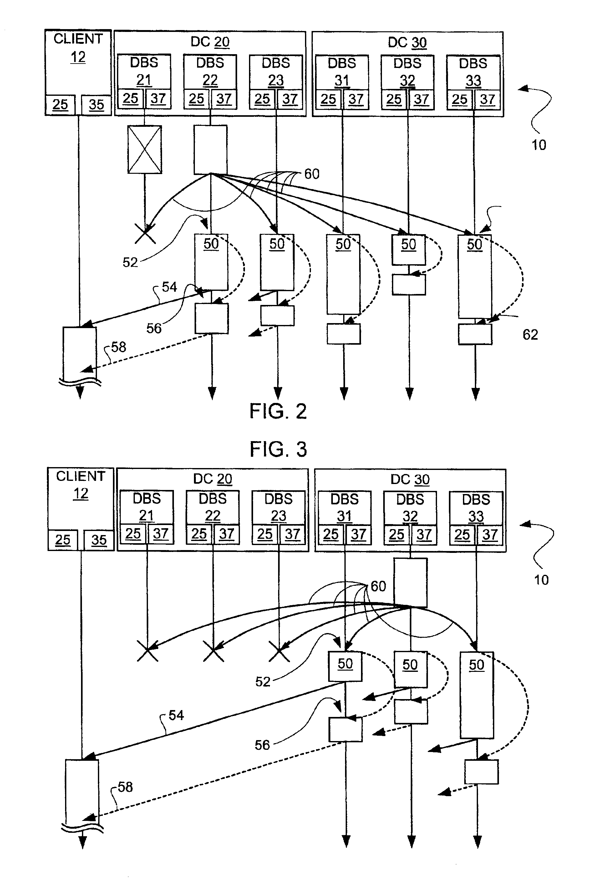
[0017]The present invention is a distributed data center system protocol that prescribes how database clients and data centers interact to achieve a common goal. The protocol consists of two parts: one is executed at the database clients, and the other at the data centers. The database clients interact with the data centers to execute transactions.

[0018]Disasters can be caused by the environment (e.g., floods, earthquakes, fires), and also a coincidence of events within the computer system itself (e.g., operator errors, simultaneous crash of critical components due to software faults). Disaster-resilient systems often rely on some replication mechanism. For example, to implement disaster recovery for a database system, a typical configuration is to have an active database in a primary data center and stand-by databases in the primary data center and in backup data centers. One of the major problems solved by the present invention is how to handle the failover of these data centers t...


PUM


Abstract

A distributed data center system protocol is provided which includes providing a client having a failure detector, a primary data center, and a backup data center operatively interconnected. A transaction operation is provided from the client to the primary database server in the primary data center and the backup database server for execution. If the client detects a failure or suspects a failure of the primary database server, the transaction operation is provided to the backup database server, which becomes the new primary database server. The database server executing the transaction operation returns the executed transaction operation to the client. If the primary data center suffers a disaster, the backup data center takes over control.

Description

TECHNICAL FIELD[0001]The present invention relates generally to a distributed data center system protocol, or method, and more specifically to a distributed data center system protocol that prescribes how database clients and data centers interact for continuity of service in the event of disasters.BACKGROUND ART[0002]For distributed data center computer systems, disasters can be caused by the environment (e.g., floods, earthquakes, fires), and also a coincidence of events within the computer system itself (e.g., operator errors, simultaneous crash of critical components due to software faults). To deal with environment disasters, computer systems typically run in multiple geographically dispersed data centers, which consist of interconnected database servers with independent failure mode. Data centers are connected through possibly redundant wide-area network links, and typically operate in a primary-backup manner; i.e., if the primary data center suffers a disaster, the backup dat...

Claims


Application Information

Patent Timeline
Patent Type & Authority Patents(United States)
IPC IPC(8): G06F11/20
CPCG06F11/2041G06F11/2097Y10S707/99953
Inventor PEDONE, FERNANDOFROLUND, SVEND
Owner HEWLETT-PACKARD ENTERPRISE DEV LP
Why Eureka
Try Eureka