Liquid level detecting device

a detection device and liquid level technology, applied in liquid/fluent solid measurement, instruments, machines/engines, etc., can solve problems such as impaired response in liquid level detection

Active Publication Date: 2008-09-25
DENSO CORP
View PDF4 Cites 28 Cited by
  • Summary
  • Abstract
  • Description
  • Claims
  • Application Information

AI Technical Summary

Problems solved by technology

Accordingly, the magnet holder hardly rotate promptly to change in the liquid level, and consequently response in the liquid level detection may be impaired.

Method used


Image

  • Liquid level detecting device
  • Liquid level detecting device
  • Liquid level detecting device

Examples


first embodiment

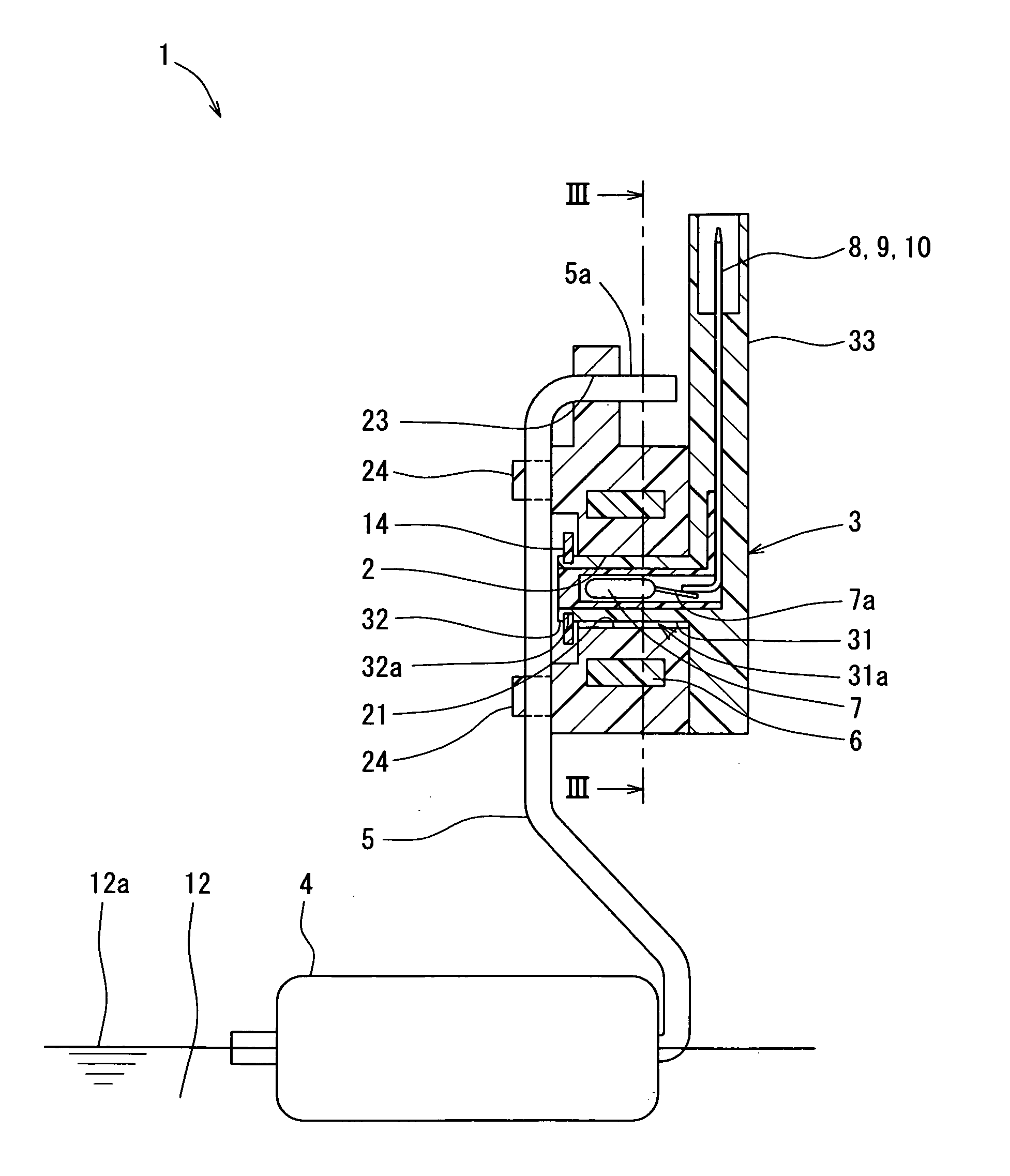
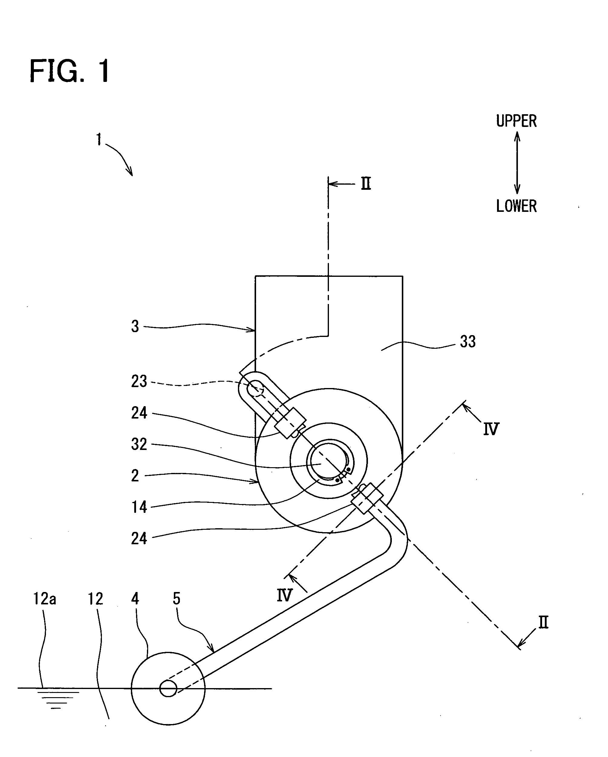
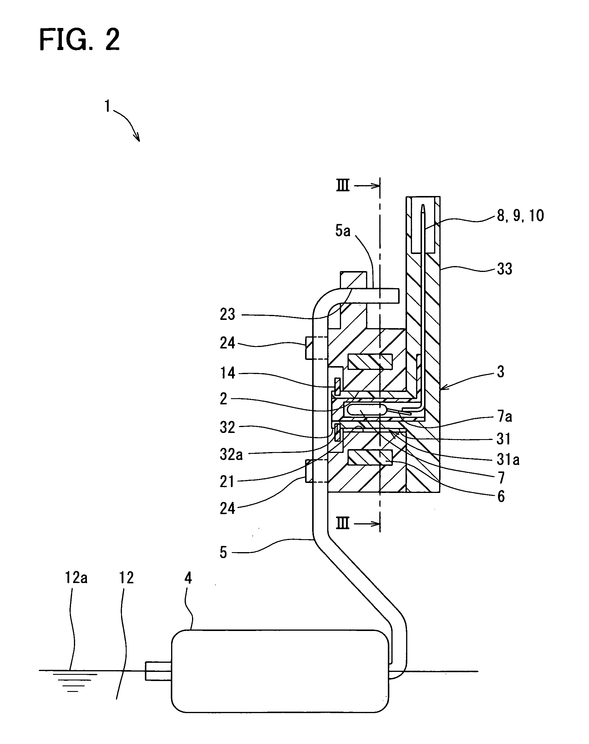
[0018]As shown in FIGS. 1, 6, a lubricating oil level gauge 1 as a liquid level detecting device is provided to an oil sump 13 (FIG. 6) to detect a liquid level of the oil sump 13. The oil sump 13 is a container of fluid such as lubricating oil.

[0019]First, a lubricating oil circuit of an engine of the vehicle is described. As shown in FIG. 6, the lubricating oil circuit of the engine includes the oil sump 13, an oil pump 102, an oil filter 103, and movable components 104 of the engine, which are connected with each other via a pipe member, a lubricating oil passage provided in a main body of the engine, and the like. The oil pump 102 feeds lubricating oil from the oil sump 13 to the oil filter 103. The lubricating oil is removed of a foreign matter or the like by passing through the oil filter 103. Thereafter, the lubricating oil is supplied to each of the movable components 104. The movable components 104 include, for example, a camshaft, a bearing of the crankshaft, a sliding por...


PUM


Abstract

A liquid level detecting device includes a rotative member having a bearing portion and a stationary member having an axis portion. The axis portion is fitted to a hole of the bearing portion, thereby rotatably holding the rotative member. The rotative member is integrated with a displacement member. The stationary member is fixed with a detection unit to detect a displacement of the displacement member. The rotative member is connected with a float via an arm. The axis portion has an inserted portion inserted in the bearing portion and in contact with the bearing portion via a contact portion. The contact portion has a total area that is less than an area of an outer circumferential periphery of the inserted portion.

Description

CROSS REFERENCE TO RELATED APPLICATIONS[0001]This application is based on and incorporates herein by reference Japanese Patent Application No. 2007-73319 filed on Mar. 20, 2007.FIELD OF THE INVENTION[0002]The present invention relates to a liquid level detecting device for detecting a liquid level.BACKGROUND OF THE INVENTION[0003]For example, according to US2005 / 0083045A1 (JP-A-2005-10093), a liquid level detecting device includes a float, which floats in fluid to detect a liquid level of the fluid. The float is connected with one end of an arm. The arm is rotatably supported by a body at the other end. The other end of the arm is fixed with a magnet. The body has a magnetoresistive element as a magnetism detection element opposed to the magnet. The float moves correspondingly to change in a liquid level, so that the movement of the float is converted into a rotary motion of the arm, thereby the magnet rotates in conjunction with the liquid level. Thus, magnetic flux generated by th...

Claims


Application Information

Patent Timeline
Patent Type & Authority Applications(United States)
IPC IPC(8): G01F23/38G01B7/26
CPCG01F23/38
Inventor MIYAGAWA, ISAOYASUDA, ATSUSHI
Owner DENSO CORP
Why Eureka
Try Eureka