Protective device plate for an electrical box

a protective device and box technology, applied in the field of protective plates, can solve the problems of affecting the service life of the electrical box, so as to achieve the effect of preventing damage to the electrical box or mud ring or any wiring or devices inside, and reducing service li

Inactive Publication Date: 2008-10-02
THOMAS & BETTS INT INC
View PDF8 Cites 23 Cited by
  • Summary
  • Abstract
  • Description
  • Claims
  • Application Information

AI Technical Summary

Benefits of technology

[0009]The present invention is a protective cover for an electrical device mounting structure. The protective cover includes a generally rectangular plate having a front and a back and includes a right side wall, a left side wall, a top end wall and a bottom end wall extending downwardly from the front to form a perimetrical edge with four corners. One or more tabs extend d

Problems solved by technology

However, this requires measuring and cutting each opening and is fairly time consuming and inefficient.
While either method can be used satisfactorily to provide an opening in the wallboard for accessing the interior of the electr

Method used


Image

  • Protective device plate for an electrical box
  • Protective device plate for an electrical box
  • Protective device plate for an electrical box

Examples


Embodiment Construction

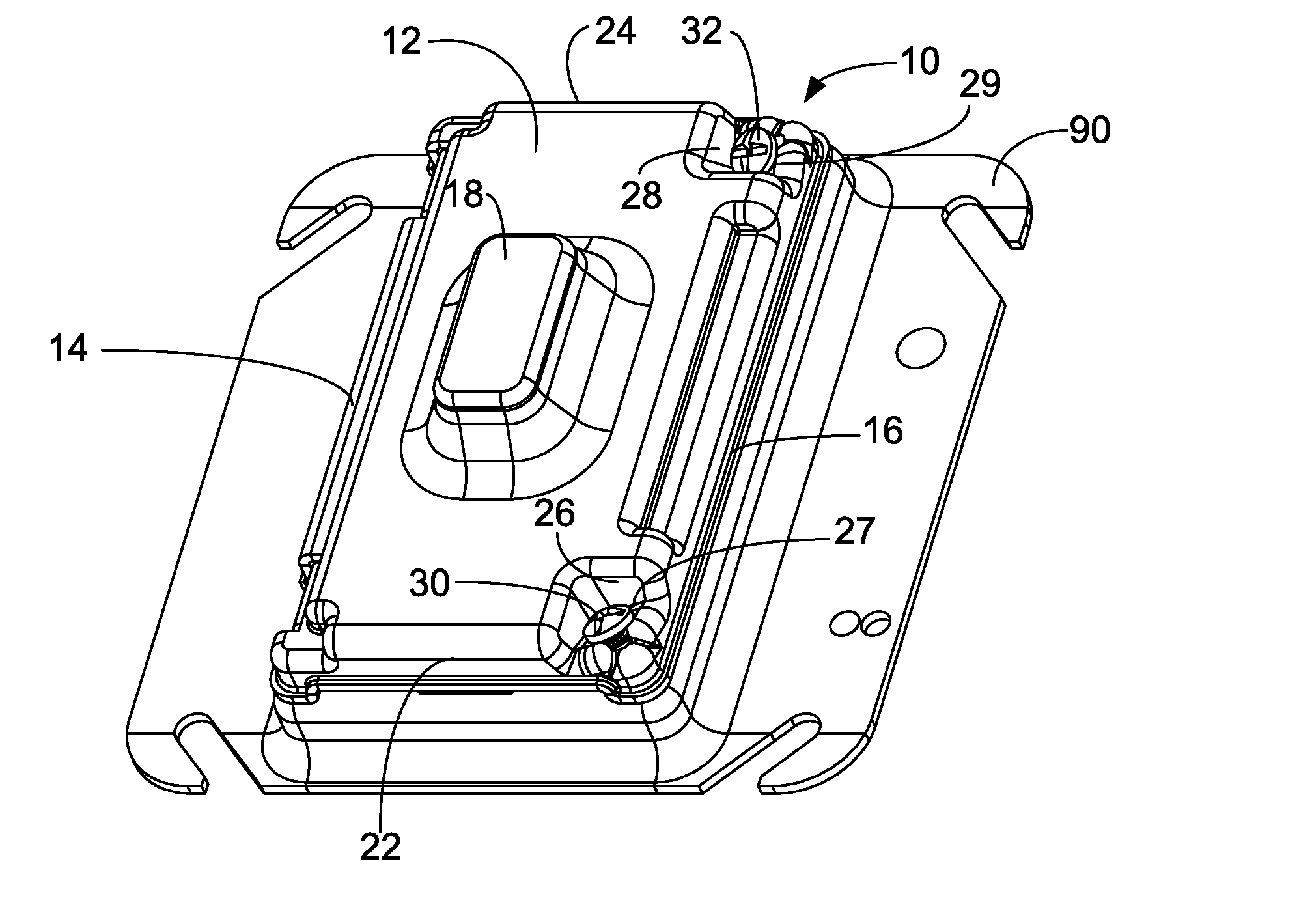
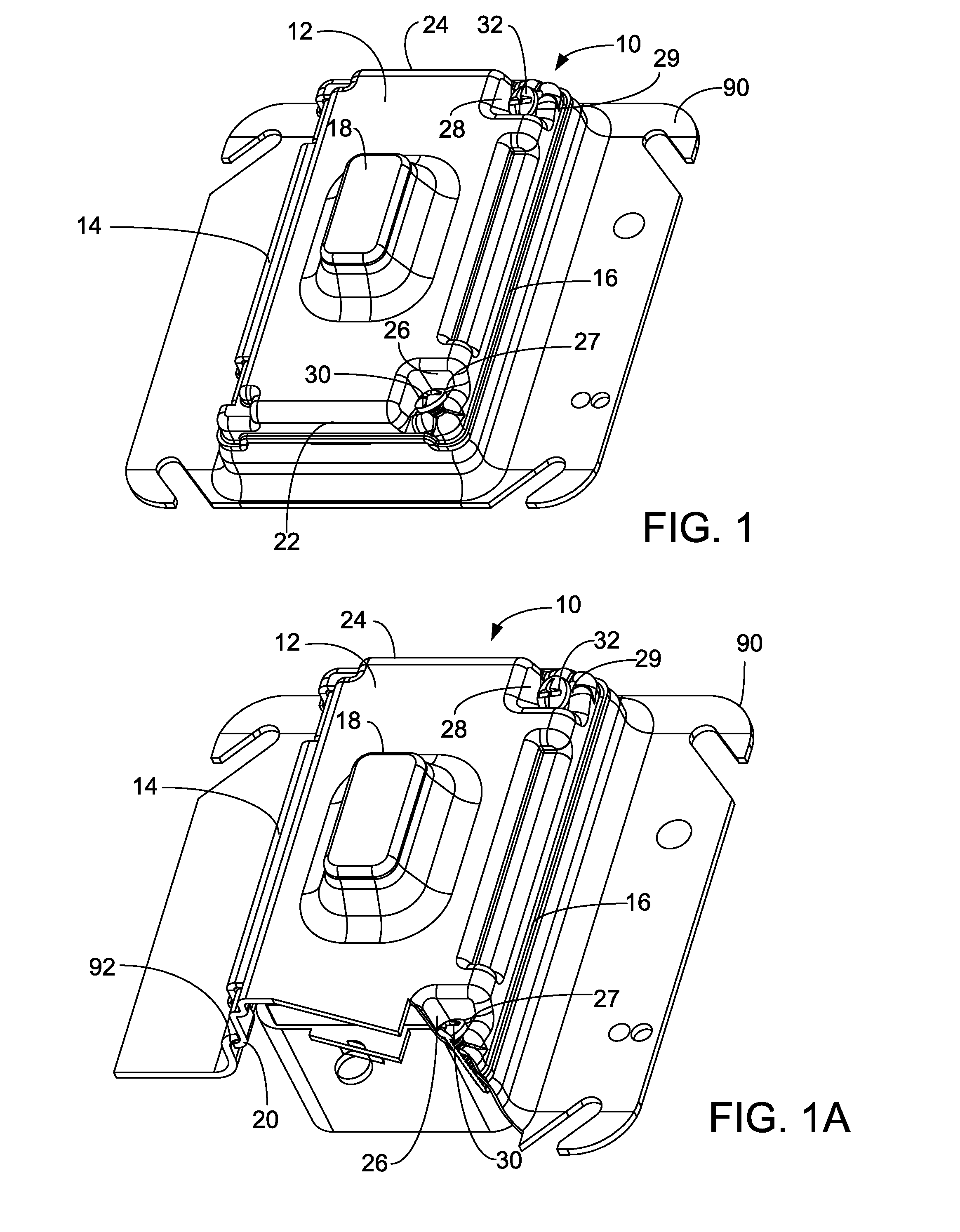
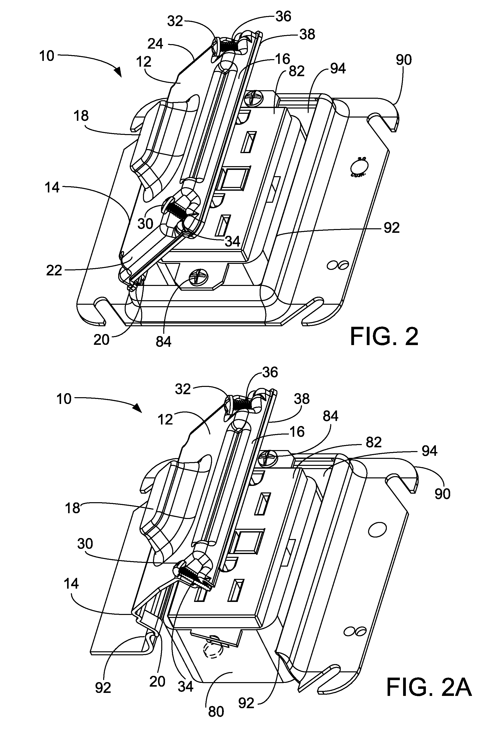
[0028]The present invention is a protective cover plate for an electrical device mounting structure (e.g., an electrical box or a mud ring) that protects the mounting structure and any electrical device that may be mounted to it from damage during construction. The protective cover plate is designed to be quickly and easily attached to and detached from the mounting structure. The protective cover plate provides protection for the mounting structure and device inside without requiring significant time and effort on the part of the user. The protective cover plate is typically mounted on an installed electrical box or mud ring to protect the box or mud ring when the wall covering is attached.

[0029]In one embodiment, the protective cover plate has one or more tabs extending from one side which engage the lip around the opening in the mounting structure and act as a hinge. The opposing side has one or more securing screws that extend under the lip when tightened to secure the cover to ...


PUM


Abstract

A protective cover for an electrical device mounting structure that includes a generally rectangular plate defined by a perimetrical edge and having a front side, a back side, a right side, a left side, a top and a bottom. The protective cover can also include one or more tabs extending from the back side for engaging the edge of the electrical device mounting structure and one or more openings in the plate for receiving a fastener for affixing the protective cover to the electrical device mounting structure.

Description

[0001]This application claims priority from provisional application Ser. No. 60 / 920,624, filed on Mar. 29, 2007, which is incorporated herein in its entirety.FIELD OF THE INVENTION[0002]The present invention relates to a protective plate for covering an electrical box or mud ring. More particularly, the invention relates to an easily installed and removed protective plate for covering an electrical box or mud ring during construction.BACKGROUND OF THE INVENTION[0003]In new wall constructions, electrical receptacle boxes and / or mud rings are typically installed on wall studs before the wallboard or sheetrock material is attached to the studs. Wallboard material typically used in residential and commercial installations is formed by a solid gypsum core product with a paperboard covering. Most commonly, it is used in 4′×8′ sheets with thicknesses ranging between ⅜″ to ¾″, although other dimensions are available such as 4′×10′ and 4′×12′ sheets. In one type of installation, the openings...

Claims


Application Information

Patent Timeline
IPC IPC(8): H02G3/14
CPCH02G3/14
Inventor DE LA BORBOLLA, IAN RUBIN
Owner THOMAS & BETTS INT INC
Why Eureka
Try Eureka