Vacuum suction cup mechanical carrying device plate carrying device

A vacuum suction cup and handling device technology, applied in the field of machinery, can solve the problems of uneven placement of sheets, uncertain feeding position, and low processing efficiency, and achieve the effects of improving work efficiency, simple structure, and easy realization

Active Publication Date: 2017-05-17
上海酷铃自动化设备有限公司
View PDF4 Cites 7 Cited by
  • Summary
  • Abstract
  • Description
  • Claims
  • Application Information

AI Technical Summary

Problems solved by technology

Low handling efficiency and high labor costs
In addition, since the boards required to be loaded are multi-layer materials, the boards are not placed nea

Method used


Image

  • Vacuum suction cup mechanical carrying device plate carrying device
  • Vacuum suction cup mechanical carrying device plate carrying device
  • Vacuum suction cup mechanical carrying device plate carrying device

Examples


Embodiment Construction

[0020] In order to illustrate the technical solution of the present invention more clearly, the present invention will be further described below in conjunction with the accompanying drawings.

[0021] Such as Figure 1-4 Shown:

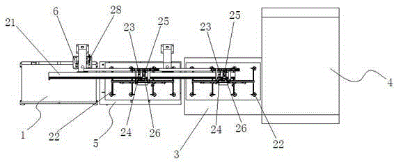
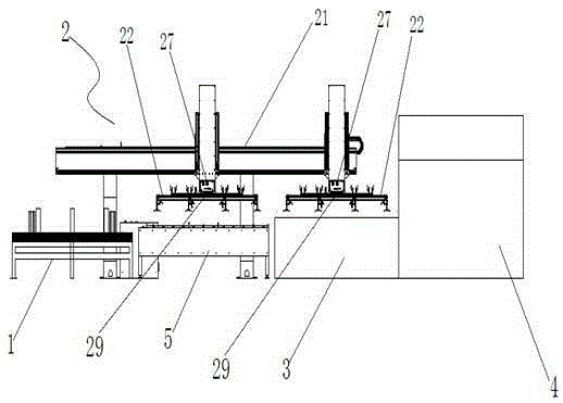
[0022] A vacuum suction cup manipulator sheet material handling device, comprising a feeding platform 1, a mechanical handling device 2, a working platform 3, a laser cutting machine 4, a positioning platform 5 and a compressed air storage 6.

[0023] Among them, the mechanical handling device 2 includes a mechanical frame body 21, a vacuum chuck manipulator 22, an x-axis servo motor 23, an x-axis reducer 24, a z-axis servo motor 25, a z-axis reducer 26, a vacuum solenoid valve 27, a vacuum pump 28 and a vacuum Pressure digital display 29, one end of the mechanical frame body 21 is located directly above the feeding platform 1, and the other end is located directly above the working platform 3; the x-axis servo motor 23 is connected to the x-axis re...


PUM


Abstract

The invention discloses a vacuum suction cup manipulator plate carrying device. The vacuum suction cup manipulator plate carrying device comprises a feeding platform, a mechanical carrying device, a working platform and a laser cutting machine. The mechanical carrying device comprises a mechanical frame body, vacuum suction cup manipulators, x-axis servo motors, x-axis speed reducers, z-axis servo motors, z-axis speed reducers, vacuum electromagnetic valves, a vacuum pump and vacuum pressure digital displays. One end of the mechanical frame body is located over the feeding platform, and the other end of the mechanical frame body is located over the working platform. The x-axis servo motors are connected with the x-axis speed reducers. The z-axis servo motors are connected with the z-axis speed reducers. A vacuum energy accumulator produces vacuum through the vacuum pump and stores vacuum energy. The vacuum electromagnetic valves are connected with the vacuum energy accumulator and control turn-on/off conducted by the vacuum energy accumulator over the vacuum suction cup manipulators. The vacuum pressure digital displays detect the vacuum degree of the surfaces of the vacuum suction cup manipulators. According to the vacuum suction cup manipulator plate carrying device, a plate is grabbed from the feeding platform onto the working platform through the manipulators, the labor cost is reduced, plate positioning is precise, and the working efficiency is improved.

Description

technical field [0001] The invention relates to the field of mechanical technology, in particular to a sheet material handling device for a vacuum suction cup mechanical handling device. Background technique [0002] In the existing laser cutting and CNC punching machine industries, manually placing the sheet to be cut on the laser table or the CNC table for processing requires manually transporting the sheet to a fixed position on the processing platform. The handling efficiency is low and the labor cost is extremely high. In addition, since the boards required to be loaded are multi-layer materials, the boards are not placed neatly. As a result, the unloading position is uncertain when the sheet is transported to the worktable, resulting in low efficiency in subsequent processing. Contents of the invention [0003] In order to solve the above problems, the present invention provides a vacuum suction cup mechanical handling device sheet metal handling device. [0004] ...

Claims


Application Information

Patent Timeline
IPC IPC(8): B23K26/38B23K26/70
CPCB23K26/38
Inventor 陈照文
Owner 上海酷铃自动化设备有限公司
Why Eureka
Try Eureka