
Door entry security device with electronic lock

a security device and electronic lock technology, applied in the field of door entry security devices with electronic locks, can solve the problems of system not properly armed and disarmed, user error in not arming the alarm system, and system disarming

Active Publication Date: 2008-10-02
ADEMCO INC
View PDF16 Cites 68 Cited by
  • Summary
  • Abstract
  • Description
  • Claims
  • Application Information

AI Technical Summary

Benefits of technology

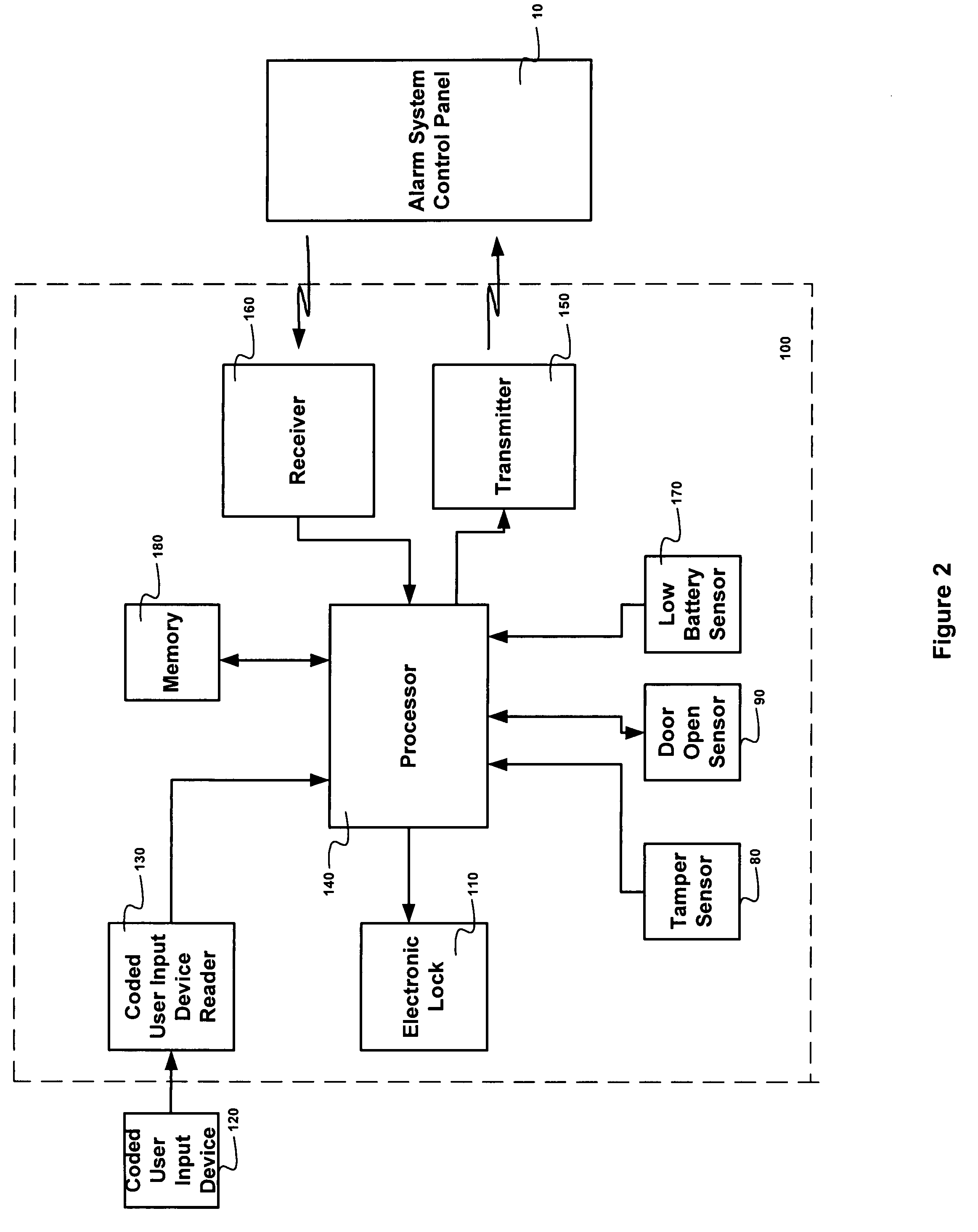
[0010]The present invention is an alarm system for assisting a user in arming and disarming the alarm system when locking and unlocking an entry door. The alarm system of the present invention includes an alarm system control panel and a door entry security device that selectively locks and unlocks the entry door. The door entry security device includes a transmitter, an electronic lock and processing circuitry. The door entry security device may also include a coded user input device reader which provides an electronic lock command to the processing circuitry. The coded user input device reader may be a mechanical token (or key) acceptor, a key fob reader, a card swipe reader, or keypad reader. The coded user input device reader authenticates the coded user input device by methods known to one skilled in the art. Once the processing circuit detects the electronic lock command, it triggers the electronic lock to perform the command and it initiates the transmitter to transmit an electronic lock status message based on the electronic lock command. The alarm system control panel receives the electronic lock status message and performs an alarm system function based on the electronic lock status message. The electronic lock status message may be an unlock message causing the alarm system control panel to disarm the alarm system, or a lock message causing the alarm system control panel to arm the alarm system. A benefit of the present invention is that the user does not have to enter an additional security code into the alarm system to arm or disarm it. It is assumed that a person who has the entry door keypad code (or key) will also be authorized to access the alarm system. The processing circuit of the door entry security device is adapted to store the electronic lock position based on the electronic lock commands. The door entry security device of the present invention does not need to sense the presence or motion of a deadbolt in the door jamb to determine the lock position as in the prior art. The door entry security device locally performs the authentication of the coded user input and controls the electronic lock, while the alarm system control panel locally performs the associated alarm function. This operation is different from other alarm systems where a central processor performs the unlock function and the alarm functions.
[0011]The door entry security device of the present invention may also contain a tamper detection device. In this embodiment, the electronic lock status message is a tamper message (transmitted when the tamper detection device determines that the door entry security device has been tampered with), causing the alarm system control panel to set off an alarm notification.
[0012]The method of automatically controlling the alarm system when locking or unlocking the entry door includes the steps of generating a coded user input signal, detecting by a door entry security device the coded user input signal, authenticating by a door entry security device the coded user input signal, transmitting from the door entry security device an electronic lock status message as a function of an electronic lock position, receiving the electronic lock status message by an alarm system control panel, processing by the alarm system control panel the electronic lock status message to generate an alarm system command, and executing the alarm system command. The cod

Problems solved by technology

Problems arise when the system is not properly armed and disarmed.
Typical problems users have include not disarming the system before the alarm sounds and the central control station is notified.
This may occur when the user unlocks and enters the home but becomes distracted or takes too long before entering the disarm code into the alarm system keypad.
Another common mistake users make is not arming the alarm system when the home is unoccupied.
This may occur when the user simply forgets to arm the alarm system possibly due to exiting a door that is not near the alarm system keypad.
Another problem that may occur is the user may forget to lock an entry door after leaving or entering the home.
If the user is away, he may worry that he has forgotten to lock the entry door.
An additional user problem may occur when he is locked out of the house.

Method used


Image

  • Door entry security device with electronic lock
  • Door entry security device with electronic lock
  • Door entry security device with electronic lock

Examples


Embodiment Construction

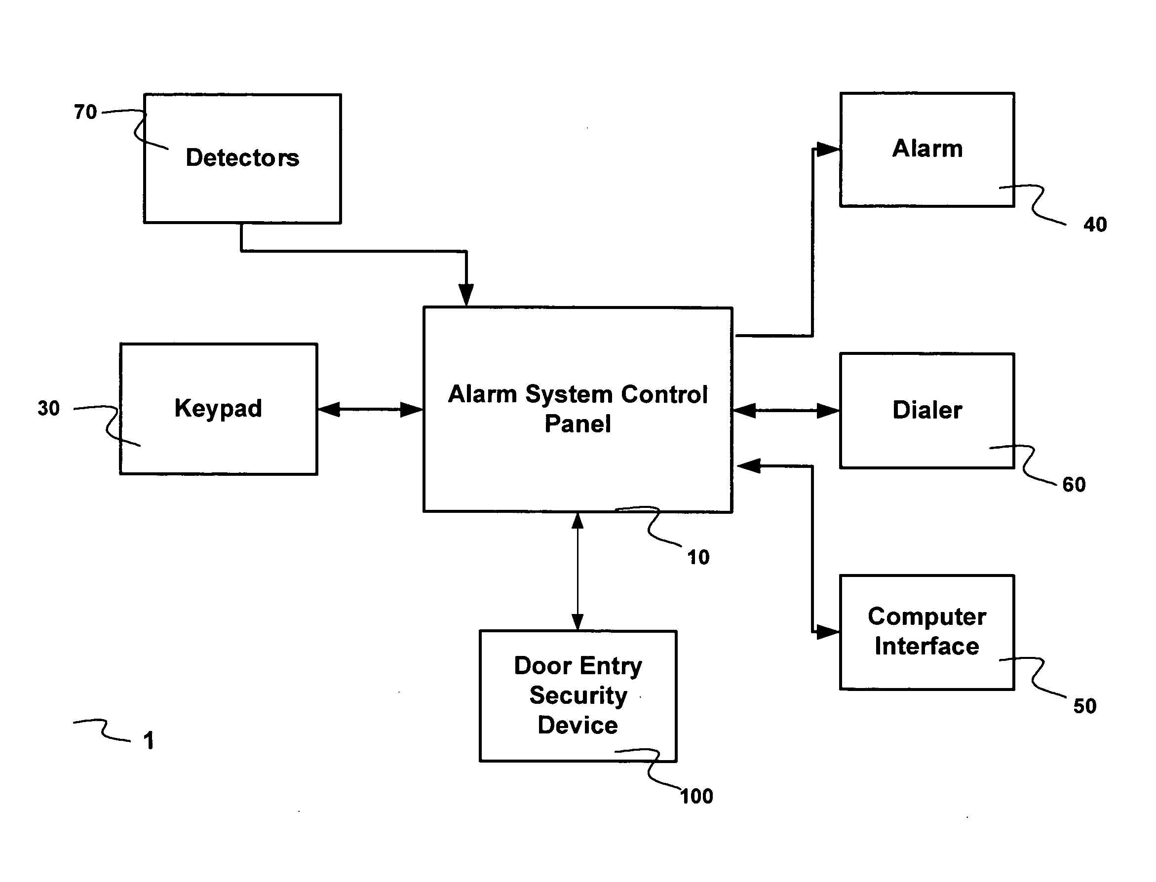
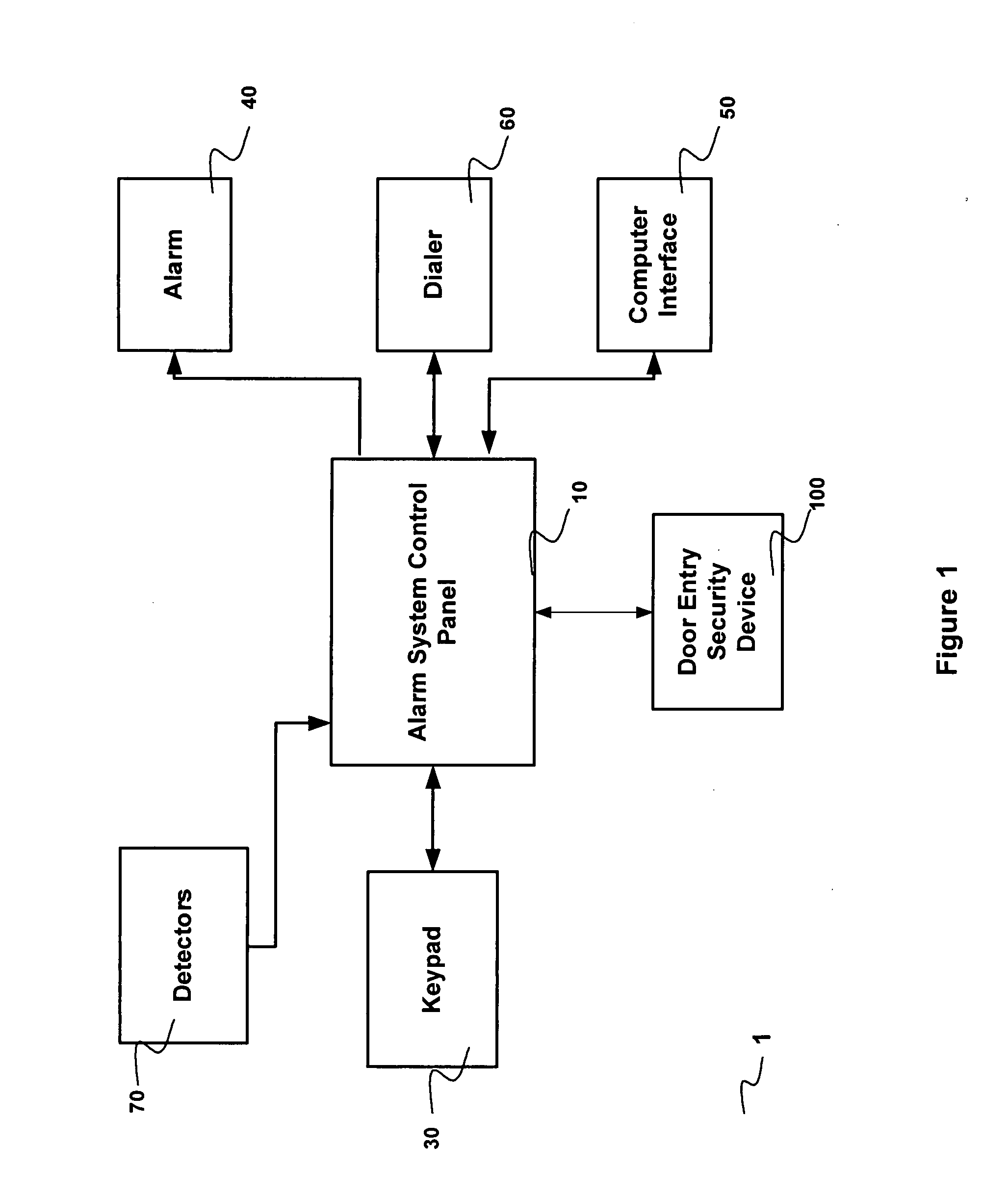
[0022]The preferred embodiments of the present invention will now be described with respect to the Figures. FIG. 1 shows a block diagram of an alarm system 1 which includes an alarm system control panel 10, an alarm 40, a dialer 60 for calls to / from a central monitoring station, a computer interface 50, a keypad 30, intrusion detectors 70 (which may be wired or wireless,) and a door entry security device 100. Novel features of the present invention include the ability of the alarm system control panel 10 to automatically arm or disarm itself based on the functions of the door entry security device 100 and the ability of the door entry security device 100 to automatically lock or unlock based on the functions of the alarm system control panel 10. In the present invention, when an entry door is unlocked, the door entry security device 100 sends an unlock message to the alarm system control panel 10 and the alarm system control panel 10 automatically disarms the alarm system 1. There i...


PUM


Abstract

An alarm system and method for (1) assisting a user in arming and disarming an alarm system when locking and unlocking an entry door, (2) automatically locking an entry door when arming the alarm system, and / or (3) remotely controlling an electronic lock in an entry door.

Description

TECHNICAL FIELD[0001]This invention relates to security systems, and in particular to an alarm system that assists a user by automatically arming or disarming when an entry door is locked or unlocked. Other features of the alarm system include automatically locking an entry door when the alarm system is armed by the user, being able to remotely lock or unlock an entry door, and preventing arming of the alarm system when a door is unlocked.BACKGROUND ART[0002]Occupants of a home usually arm their home's alarm system when they are away from their home or when they are retired for the evening. Most other times the alarm system is disarmed. When the alarm system determines that an intruder has invaded the home, it sounds a local alarm and notifies a remote central control station of the intrusion. The central control station consequently sends security personnel to investigate the intrusion. The occupants of a home feel safe knowing that if the alarm has not sounded, there has been no i...

Claims


Application Information

Patent Timeline
IPC IPC(8): E05B45/06
CPCE05B45/06G08B13/08Y10T70/5155
Inventor LINFORD, KARL M.
Owner ADEMCO INC
Learn More