Mutual Shielding of Collocated Induction Coils in Multi-Component Induction Logging Instruments

a technology of induction coils and induction logging instruments, which is applied in the field of electromagnetic induction resistivity well logging instruments, can solve the problems of not providing a measure of vertical conductivity or anisotropy, interpreting data acquired, and vulnerability of the induction logging instrument to borehole conditions, so as to reduce the attenuation of the magnetic field

Active Publication Date: 2008-10-09
BAKER HUGHES INC
View PDF34 Cites 19 Cited by
  • Summary
  • Abstract
  • Description
  • Claims
  • Application Information

AI Technical Summary

Benefits of technology

[0013]One embodiment of the invention is an apparatus for evaluating an earth formation. The apparatus includes a logging tool conveyed in a borehole. The apparatus includes a logging tool configured to be conveyed in a borehole in the earth formation. A logging tool includes a first coil defining a first dipole magnetic antenna and a second coil defining a second dipole magnetic antenna substantially orthogonal to the first dipole magnetic antenna. The apparatus also includes circuitry configured to switch the second coil between an open circuit mode and an active mode. The first and second coils may be transmitter antennas. The apparatus may further include third and fourth coils comprising receiver antennas. The apparatus may also include a third coil defining a third dipole magnetic antenna substantially orthogonal to the first dipole magnetic antenna and the second dipole magnetic antenna. When the first coil is in an active mode and a second coil is in an ope...

Problems solved by technology

Conventional induction logging devices, which tend to be sensitive only to the horizontal conductivity of the formations, do not provide a measure of vertical conductivity or of anisotropy.
One difficulty in interpreting the data acquired by a transversal induction logging tool is associated with vulnerability of its response to borehole conditions.
There are a few hardware margins and software limitations that impact a conventional transversal induction logging tool performance and result in errors appearing in the acquired data.
The general hardware problem is typically associated with an unavoidable electrical field that is irradiated by the tool induction transmitter simultaneously with the desirable magnetic field, and it happens in agreement with Maxwell's equations for the time varying field.
The transmitter electrical field interacts with remaining modules of the induction logging tool and with the formation; however, this interaction does not produce any useful information.
Indeed, due to the always-existing possibility for this field to be coupled directly into the receiver part of the sensor section through parasitic displacement currents, it introduces the noise.
When this coupling occurs, the electrical field develops undesirable electrical potentials at the input of the receiver signal conditioning, primarily across the induction coil receiver, and this voltage becomes an a...

Method used


Image

  • Mutual Shielding of Collocated Induction Coils in Multi-Component Induction Logging Instruments
  • Mutual Shielding of Collocated Induction Coils in Multi-Component Induction Logging Instruments
  • Mutual Shielding of Collocated Induction Coils in Multi-Component Induction Logging Instruments

Examples


Embodiment Construction

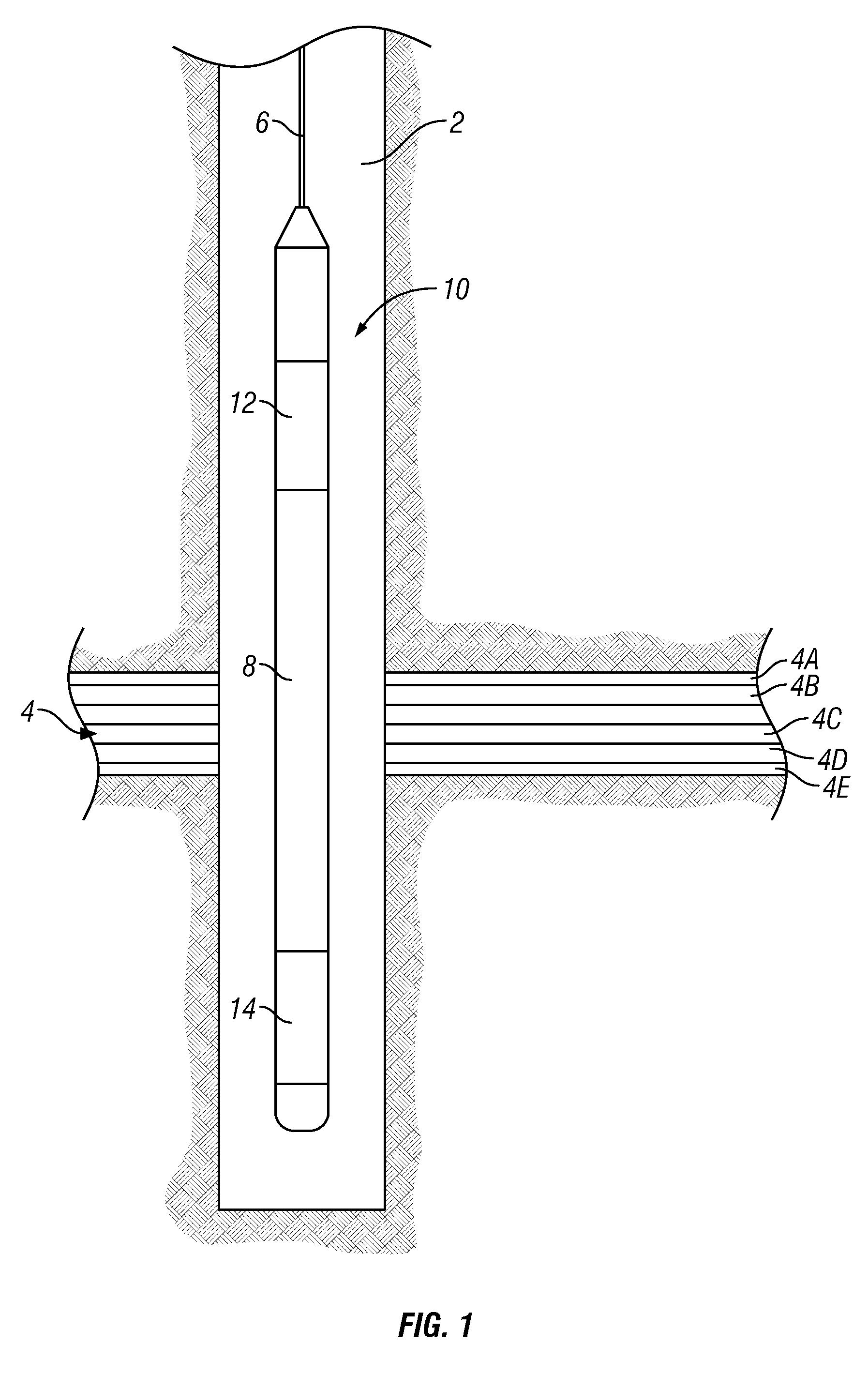
[0025]Referring now to FIG. 1, an electromagnetic induction well logging instrument 10 is shown disposed in a wellbore 2 drilled through earth formations. The earth formations are shown generally at 4. The instrument 10 can be lowered into and withdrawn from the wellbore 2 by means of an armored electrical cable 6 or similar conveyance known in the art. The instrument 10 can be assembled from three subsections: an auxiliary electronics unit 14 disposed at one end of the instrument 10; a coil mandrel unit 8 attached to the auxiliary electronics unit 14; and a receiver / signal processing / telemetry electronics unit 12 attached to the other end of the coil mandrel unit 8, this unit 12 typically being attached to the cable 6.

[0026]The coil mandrel unit 8 includes induction transmitter and receiver coils, as will be further explained, for inducing electromagnetic fields in the earth formations 4 and for receiving voltage signals induced by eddy currents flowing in the earth formations 4 as...


PUM


Abstract

In a multicomponent logging tool, a coil is electrically isolated by open circuiting another, substantially orthogonal coil.

Description

BACKGROUND OF THE INVENTION[0001]1. Field of the Invention[0002]The invention is related generally to the field of electromagnetic induction resistivity well logging instruments wherein the induction antennas are oriented transversely with respect to the longitudinal axis of the instrument. More specifically, the invention is related to an apparatus for transverse electromagnetic induction resistivity well logging operating in the frequency and / or time domain with reduced errors introduced into the acquired logging data.[0003]2. Description of the Related Art[0004]Electromagnetic induction resistivity well logging instruments are well known in the art. Electromagnetic induction resistivity well logging instruments are used to determine the electrical conductivity, and its converse, resistivity, of earth formations penetrated by a borehole. Formation conductivity has been determined based on results of measuring the magnetic field of eddy currents that the instrument induces in the f...

Claims


Application Information

Patent Timeline
IPC IPC(8): G01V3/18
CPCG01V3/28
Inventor FORGANG, STANISLAV W.GOLD, RANDYPELEGRI, LUIS M.
Owner BAKER HUGHES INC
Why Eureka
Try Eureka