Reflector Antenna

a technology of reflector antennas and antennas, applied in the field of electromagnetic radiation, can solve the problems of attenuation or signal loss of antennas outdoors, various difficulties in attenuating or reducing the effect of nois

Inactive Publication Date: 2008-08-28
KHARADLY MOSTAFA M
View PDF10 Cites 235 Cited by
  • Summary
  • Abstract
  • Description
  • Claims
  • Application Information

AI Technical Summary

Benefits of technology

[0005]The present inventor has previously studied the effects of wet antenna attenuation on propagation data statistics. The present inventor has concluded that the dominant source of attenuation or signal loss caused by rain arises from wet surfaces of the radome, or from other wet radiating surfaces associated with the feed. The present inventor has also concluded that wetness of the reflector dish itself results in comparatively minor attenuation, and attenuation from the instantaneous rate of rain falling through the air between the feed and the reflector tends to be negligible in comparison to attenuation caused by wet antenna surfaces.

Problems solved by technology

However, locating antennas outdoors poses various difficulties, including attenuation or signal loss when the antenna is exposed to rain.

Method used


Image

  • Reflector Antenna
  • Reflector Antenna
  • Reflector Antenna

Examples


first embodiment

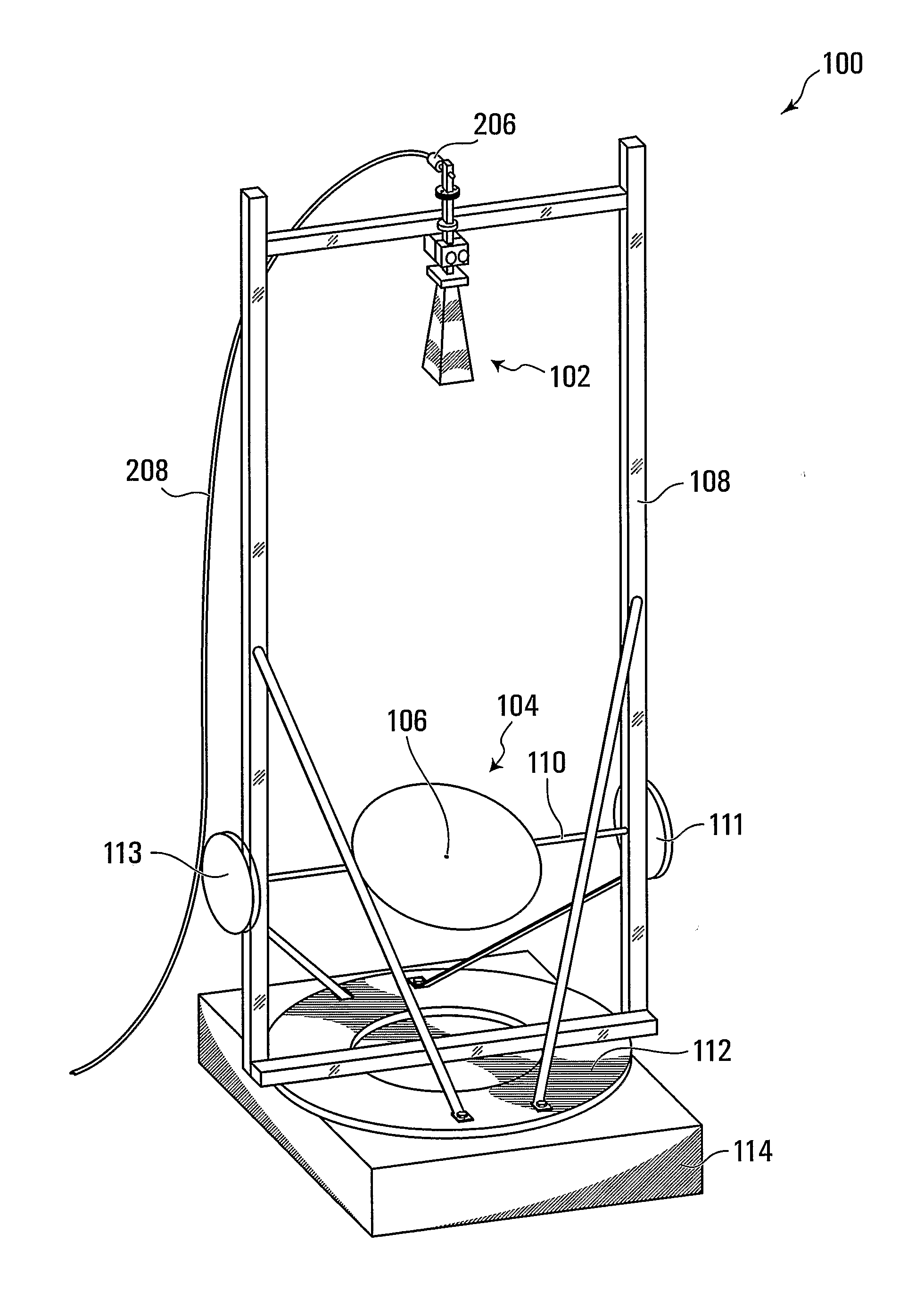
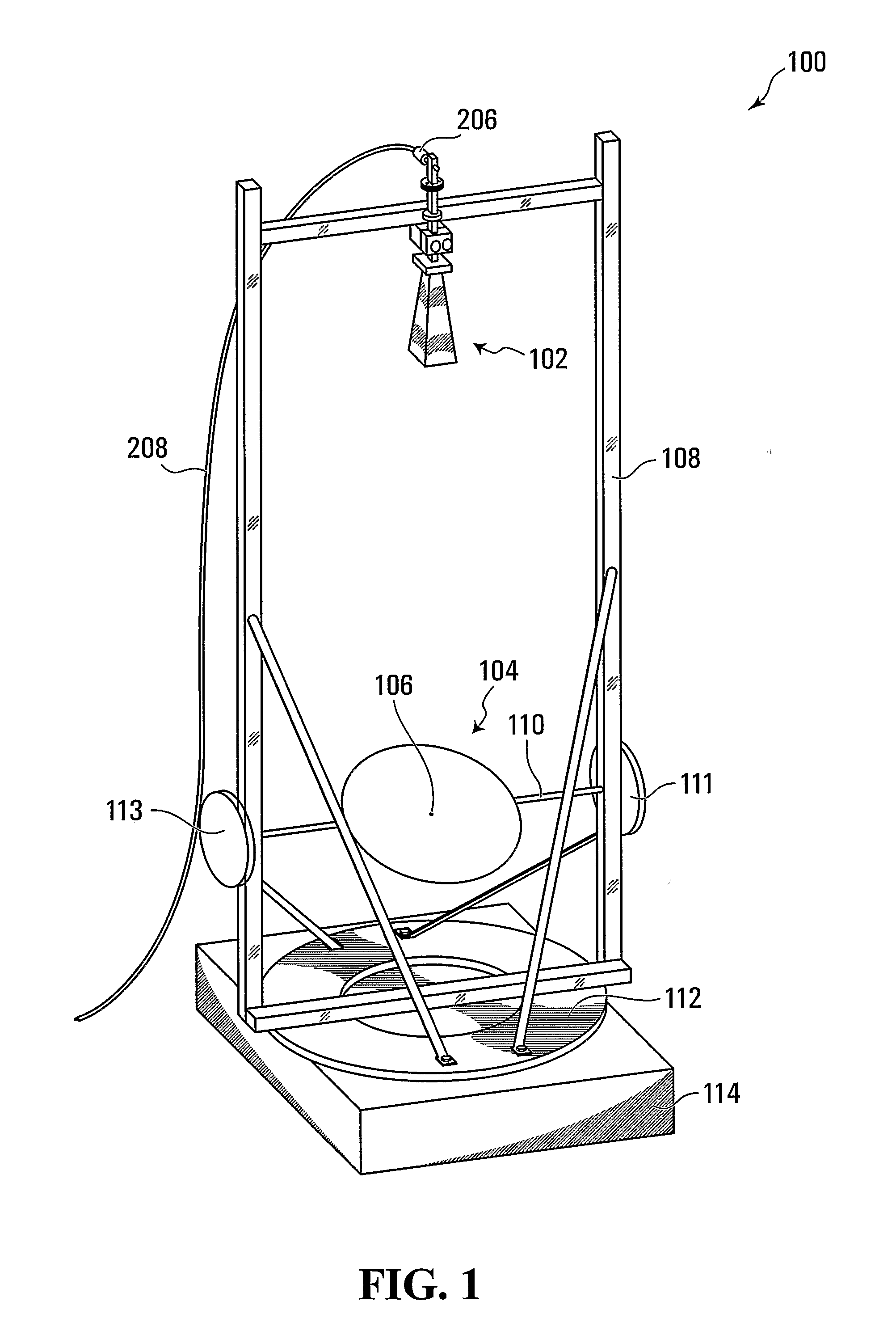
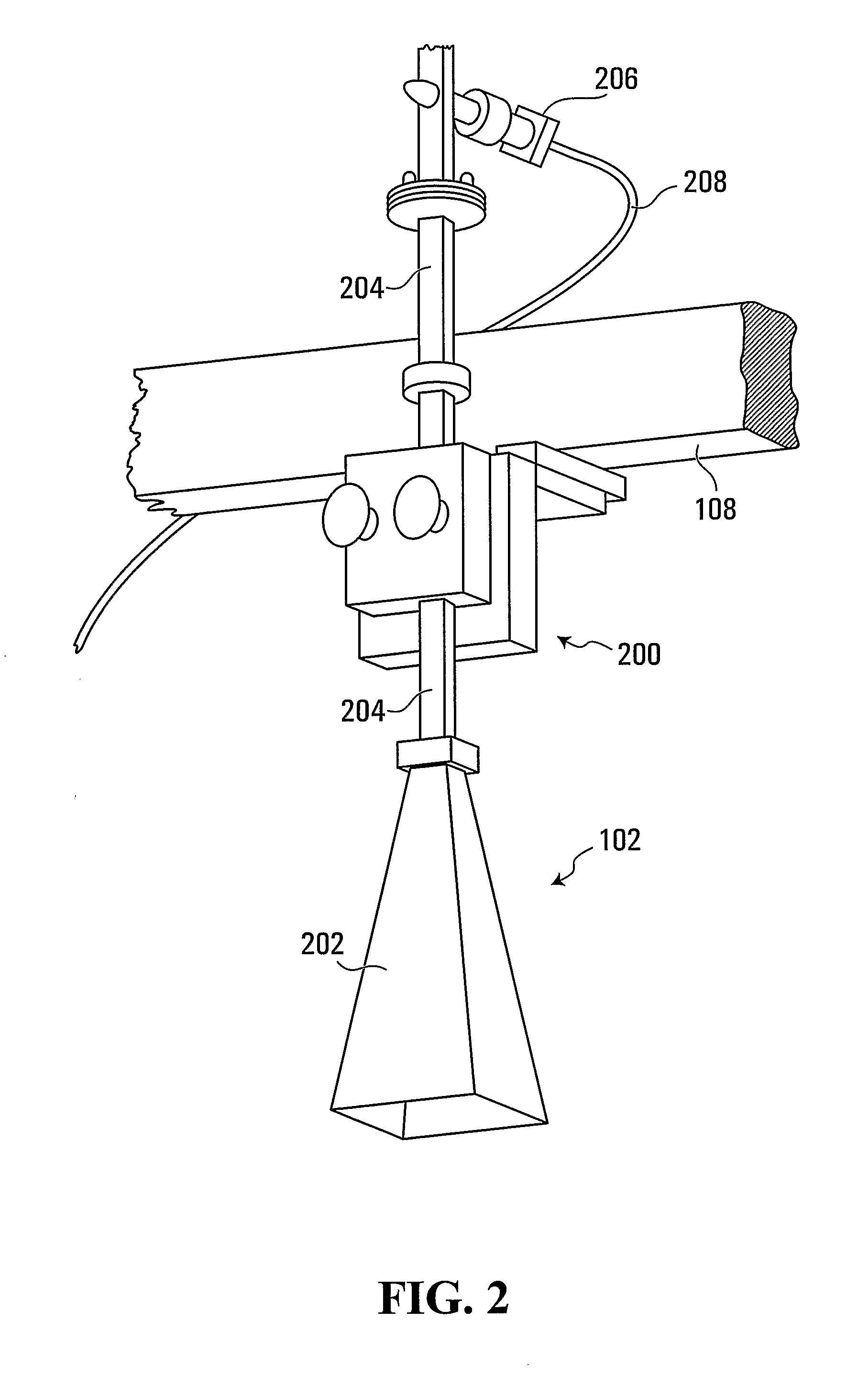
[0037]Referring to FIG. 1, a reflector antenna according to the invention is shown generally at 100. In this embodiment, the antenna 100 includes a feed shown generally at 102, and a reflector shown generally at 104. In the present embodiment, the feed 102 is configured to always point during operation in a direction that opposes ingress of water into the feed.

[0038]In this embodiment, the reflector 104 has a truncated spherical reflecting surface 106. Additionally in the present embodiment, the reflector 104 is spaced apart from the feed 102 by a focal length at least as great as a diameter of the reflector, as discussed in greater detail below.

[0039]In this embodiment, a relative orientation of the reflector 104 and the feed 102 is adjustable. To achieve this, in this embodiment the reflector is rotatable about each of two perpendicular axes. One of the axes is a vertical axis for azimuthal rotation of the reflector thereabout and the other one of the axes is a horizontal axis for...

second embodiment

[0063]Referring to FIGS. 1 and 4, a reflector according to the invention is shown generally at 400 in FIG. 4. Unlike the solid reflecting surface 106 of the reflector 104 shown in FIG. 1, in this embodiment a reflecting surface 402 of the reflector 400 includes at least one aperture shown generally at 404 through the reflecting surface. More particularly, in this embodiment the at least one aperture 404 includes a plurality of drainage apertures. In this embodiment, each of the apertures has a diameter less than one-eighth of a wavelength intended to be reflected by the reflector. More particularly, in this embodiment each of the apertures has a diameter less than one-twentieth of a wavelength intended to be reflected by the reflector. In this regard, it will be appreciated that in general, holes in a reflecting surface that are smaller than one-twentieth of the wavelength to be reflected do not appreciably reduce the intensity of reflection of that wavelength by the reflecting surf...

third embodiment

[0064]Similarly, referring to FIG. 5, a reflector according to the invention is shown generally at 500 in FIG. 4. In this embodiment, a reflecting surface 502 of the reflector 500 includes at least one aperture. More particularly, in this embodiment the at least one aperture includes a plurality of drainage apertures. More particularly still, in the present embodiment the reflector 500 is constructed as a truncated, spherically curved lattice, defining apertures between intersecting perpendicular lattice strips. As with the previous embodiment, in this embodiment each of the apertures has a diameter less than one-eighth of a wavelength intended to be reflected by the reflector, and preferably less than one-twentieth of a wavelength intended to be reflected by the reflector.

[0065]Although a specific frame 108 was described in connection with the embodiment shown in FIG. 1, alternatively, any other suitable way of mounting the reflector and the feed may be substituted.


PUM


Abstract

A reflector antenna includes a feed configured to always point during operation in a direction that opposes ingress of water into the feed, and a reflector having a truncated spherical reflecting surface, wherein a relative orientation of the reflector and the feed is adjustable. Another reflector antenna includes a feed configured to always point during operation in a direction that opposes ingress of water into the feed, and a reflector spaced apart from the feed by a focal length at least as great as a diameter of the reflector. Another reflector antenna includes a feed and a reflector having a truncated spherical reflecting surface, wherein the reflector is spaced apart from the feed by a focal length at least as great as a diameter of the reflector.

Description

CROSS-REFERENCE TO RELATED APPLICATIONS[0001]This application claims the benefit of priority from U.S. patent application Ser. No. 60 / 662,822 filed Mar. 18, 2005, and from U.S. patent application Ser. No. 60 / 719,600 filed Sep. 23, 2005.FIELD OF THE INVENTION[0002]The present invention relates to electromagnetic radiation such as radio waves for example, and more particularly, to reflector antennas.BACKGROUND OF THE INVENTION[0003]Many applications involve the use of reflector antennas. For example, satellite communications in frequency bands such as the Ka-band typically rely upon ground-based reflector antennas to transmit communication signals to and receive communication signals from orbiting satellites. Such satellites have either geosynchronous orbits (so that the orientation of the antenna may be fixed, always pointing at the satellite) or non-geosynchronous orbits (requiring the antenna to scan across the sky to track a satellite's path). A typical reflector antenna includes ...

Claims


Application Information

Patent Timeline
Patent Type & Authority Applications(United States)
IPC IPC(8): H01Q19/10H01Q13/00
CPCH01Q1/02H01Q1/125H01Q19/132H01Q3/20H01Q3/08
Inventor KHARADLY, MOSTAFA M.
Owner KHARADLY MOSTAFA M
Why Eureka
Try Eureka