Reflector antenna
a technology of reflector antennas and antennas, applied in the field of electromagnetic radiation, can solve the problems of attenuation or signal loss of antennas outdoors, various difficulties in attenuating or reducing the effect of nois
- Summary
- Abstract
- Description
- Claims
- Application Information
AI Technical Summary
Benefits of technology
Problems solved by technology
Method used
Image
Examples
first embodiment
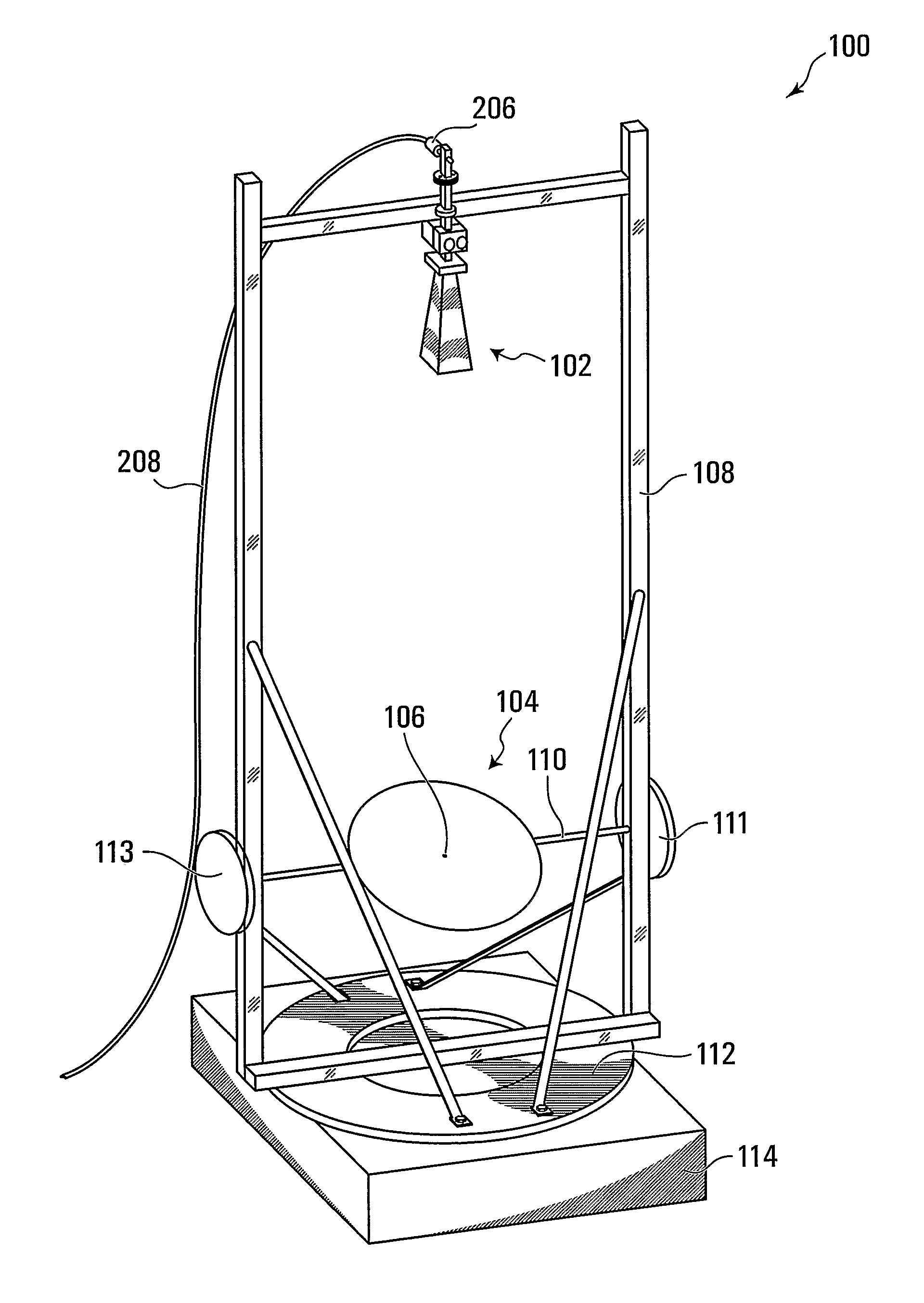
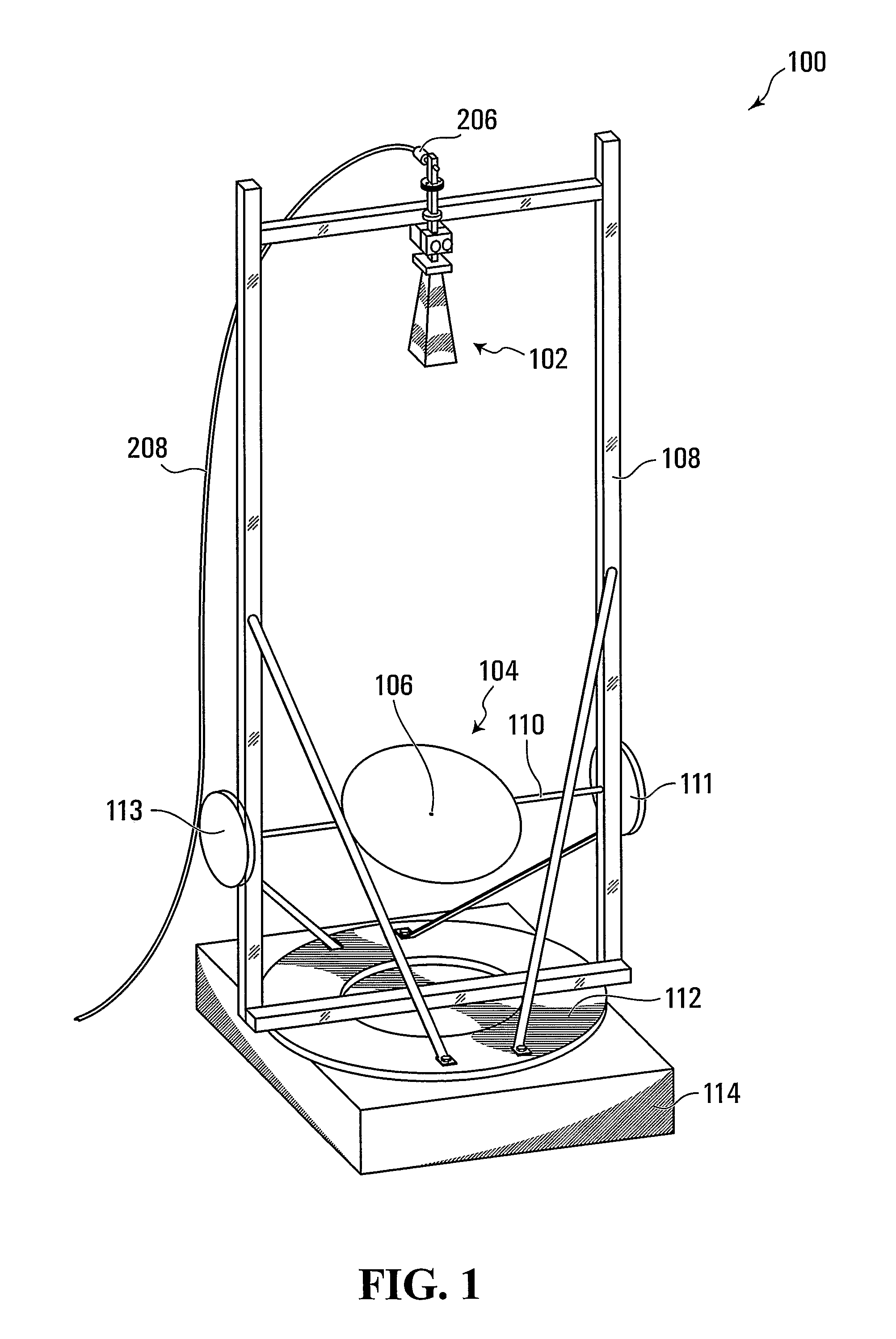
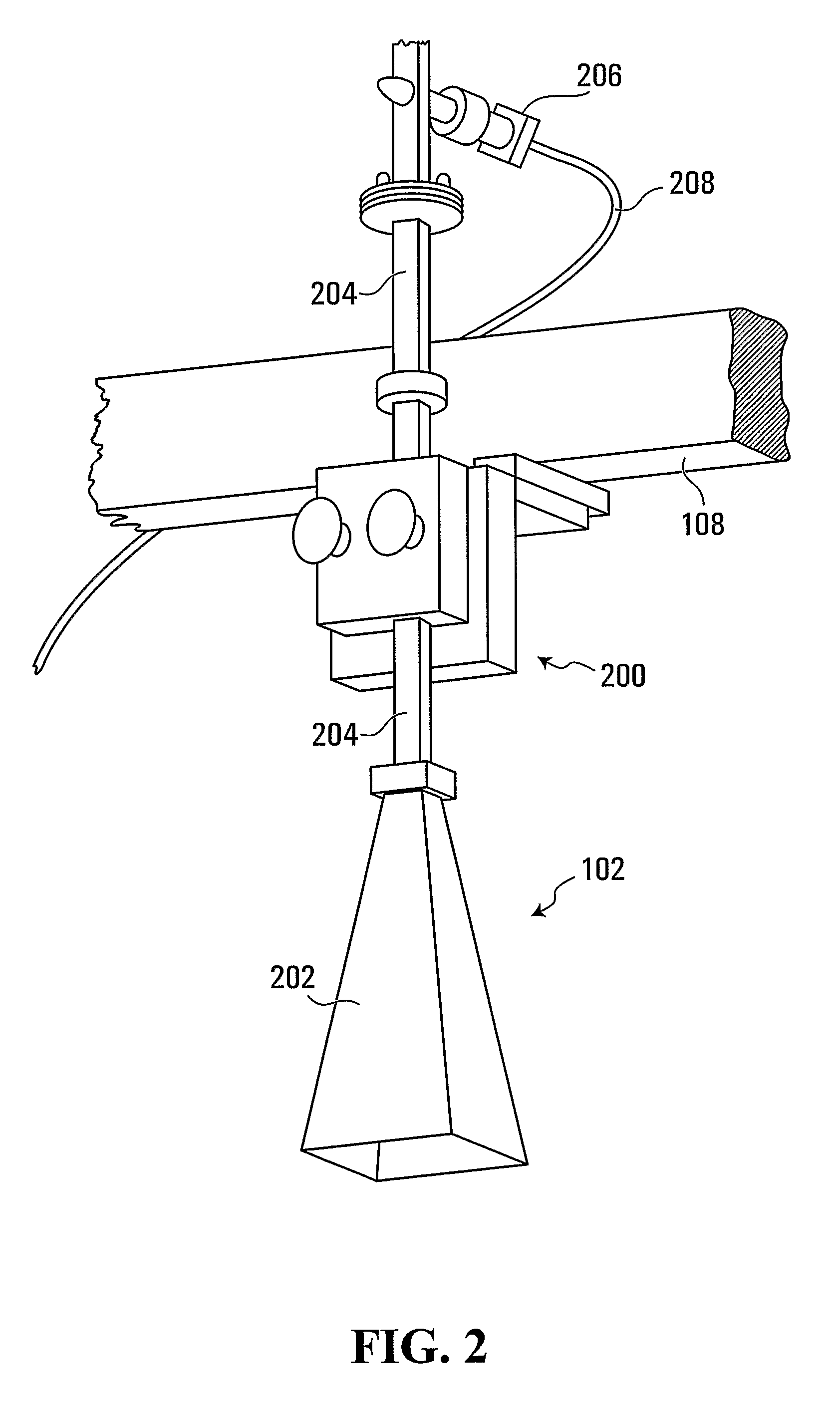
[0036]Referring to FIG. 1, a reflector antenna according to the invention is shown generally at 100. In this embodiment, the antenna 100 includes a feed shown generally at 102, and a reflector shown generally at 104. In the present embodiment, the feed 102 is configured to always point during operation in a direction that opposes ingress of water into the feed.
[0037]In this embodiment, the reflector 104 has a truncated spherical reflecting surface 106. Additionally in the present embodiment, the reflector 104 is spaced apart from the feed 102 by a focal length at least as great as a diameter of the reflector, as discussed in greater detail below.
[0038]In this embodiment, a relative orientation of the reflector 104 and the feed 102 is adjustable. To achieve this, in this embodiment the reflector is rotatable about each of two perpendicular axes. One of the axes is a vertical axis for azimuthal rotation of the reflector thereabout and the other one of the axes is a horizontal axis for...
second embodiment
[0067]Referring to FIGS. 1 and 4, a reflector according to the invention is shown generally at 400 in FIG. 4. Unlike the solid reflecting surface 106 of the reflector 104 shown in FIG. 1, in this embodiment a reflecting surface 402 of the reflector 400 includes at least one aperture shown generally at 404 through the reflecting surface. More particularly, in this embodiment the at least one aperture 404 includes a plurality of drainage apertures. In this embodiment, each of the apertures has a diameter less than one-eighth of a wavelength intended to be reflected by the reflector. More particularly, in this embodiment each of the apertures has a diameter less than one-twentieth of a wavelength intended to be reflected by the reflector. In this regard, it will be appreciated that in general, holes in a reflecting surface that are smaller than one-twentieth of the wavelength to be reflected do not appreciably reduce the intensity of reflection of that wavelength by the reflecting surf...
third embodiment
[0068]Similarly, referring to FIG. 5, a reflector according to the invention is shown generally at 500 in FIG. 4. In this embodiment, a reflecting surface 502 of the reflector 500 includes at least one aperture. More particularly, in this embodiment the at least one aperture includes a plurality of drainage apertures. More particularly still, in the present embodiment the reflector 500 is constructed as a truncated, spherically curved lattice, defining apertures between intersecting perpendicular lattice strips. As with the previous embodiment, in this embodiment each of the apertures has a diameter less than one-eighth of a wavelength intended to be reflected by the reflector, and preferably less than one-twentieth of a wavelength intended to be reflected by the reflector.
[0069]Although a specific frame 108 was described in connection with the embodiment shown in FIG. 1, alternatively, any other suitable way of mounting the reflector and the feed may be substituted.
PUM
 Abstract
Description
Claims
Application Information
 - R&D
- Intellectual Property
- Life Sciences
- Materials
- Tech Scout
- Unparalleled Data Quality
- Higher Quality Content
- 60% Fewer Hallucinations
Browse by: Latest US Patents, China's latest patents, Technical Efficacy Thesaurus, Application Domain, Technology Topic, Popular Technical Reports.
© 2025 PatSnap. All rights reserved.Legal|Privacy policy|Modern Slavery Act Transparency Statement|Sitemap|About US| Contact US: help@patsnap.com


