Crown molding and door installation tools

a crown molding and installation tool technology, applied in the direction of manufacturing tools, metal working devices, constructions, etc., can solve the problems of confusing the compound angle, difficult or complicated forming or cutting the compound angle such that the crown moldings seamlessly mate with each other, and incorrect compound angle cutting

Inactive Publication Date: 2008-10-16
KHAN VIKTOR
View PDF5 Cites 23 Cited by
  • Summary
  • Abstract
  • Description
  • Claims
  • Application Information

AI Technical Summary

Benefits of technology

[0015]In relation to the door installation jig, the same may have a U-shaped channel with an inflatable tube disposed within the channel

Problems solved by technology

One of the difficult steps in installing the crown molding is forming the joint at the corner of the room.
Unfortunately, forming or cutting the compound angle such that the crown moldings seamlessly mate with each other is difficult or complicated even for a professional installer.
Additionally, it is also confusing to keep track of the compound angle cut for the first and second crown molding.
Typically, even those with experience in installing crown molding may mistakenly make an incorrect compound angle cut.
Another deficiency in prior art miter saws for cutting compound angle cuts in crown molding is that prior art miter saws are pre marked for ninety degree walls such that the installer may set the saw blade to the pre marked angles

Method used


Image

  • Crown molding and door installation tools
  • Crown molding and door installation tools
  • Crown molding and door installation tools

Examples


first embodiment

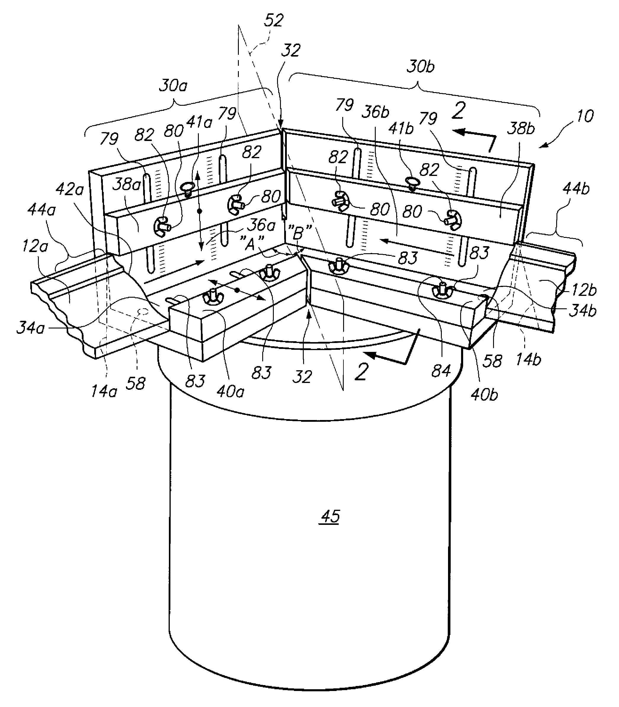
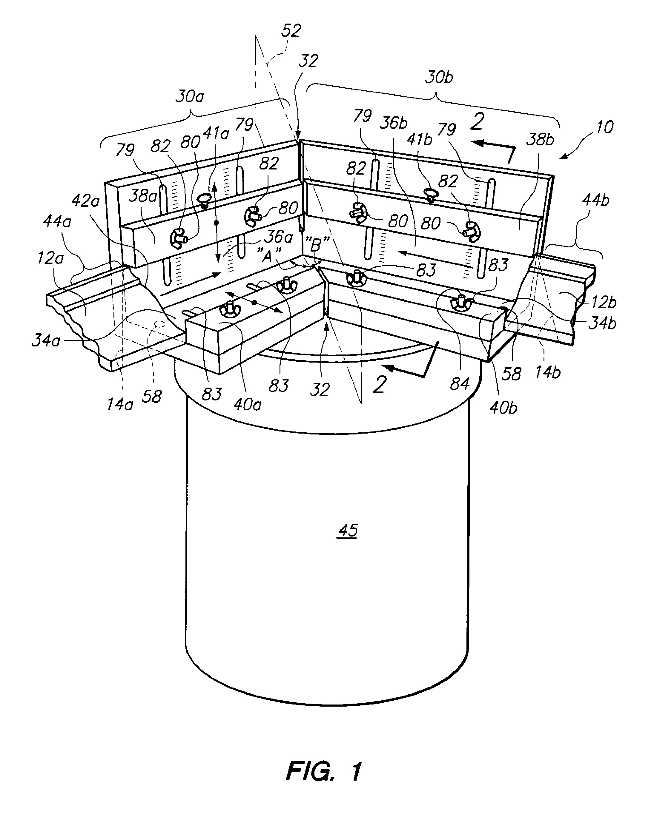
[0028]In the crown molding jig 10, the same may have three different guides 30a, b and 32, as shown in FIG. 1. Guides 30a, b are respectively for the first and second crown moldings 12a, b. The guide 32 guides the saw blade 52 to cut the compound angle cuts in the crown moldings 12a, b.

[0029]Each of the guides 30a, b for the crown molding 12a, b may have a bed surface 34a, b for resting the crown molding 12a, b while cutting the crown molding 12a, b. Each of the guides 30a, b for the crown molding 12,b may also have a back surface 36a, b for propping the crown molding 12a, b up at a particular angle. The back surface 36a, b may form a 90° angle with the bed surface 34a, b. The first and second guides 30a, b may have an upper block 38a, b and a lower block 40a, b which rotationally locks the crown molding 12a, b in the guide 30a, b about a longitudinal axis of the respective guides 30a, b such that the crown molding 12a, b does not rotate about the longitudinal axis of its respectiv...

second embodiment

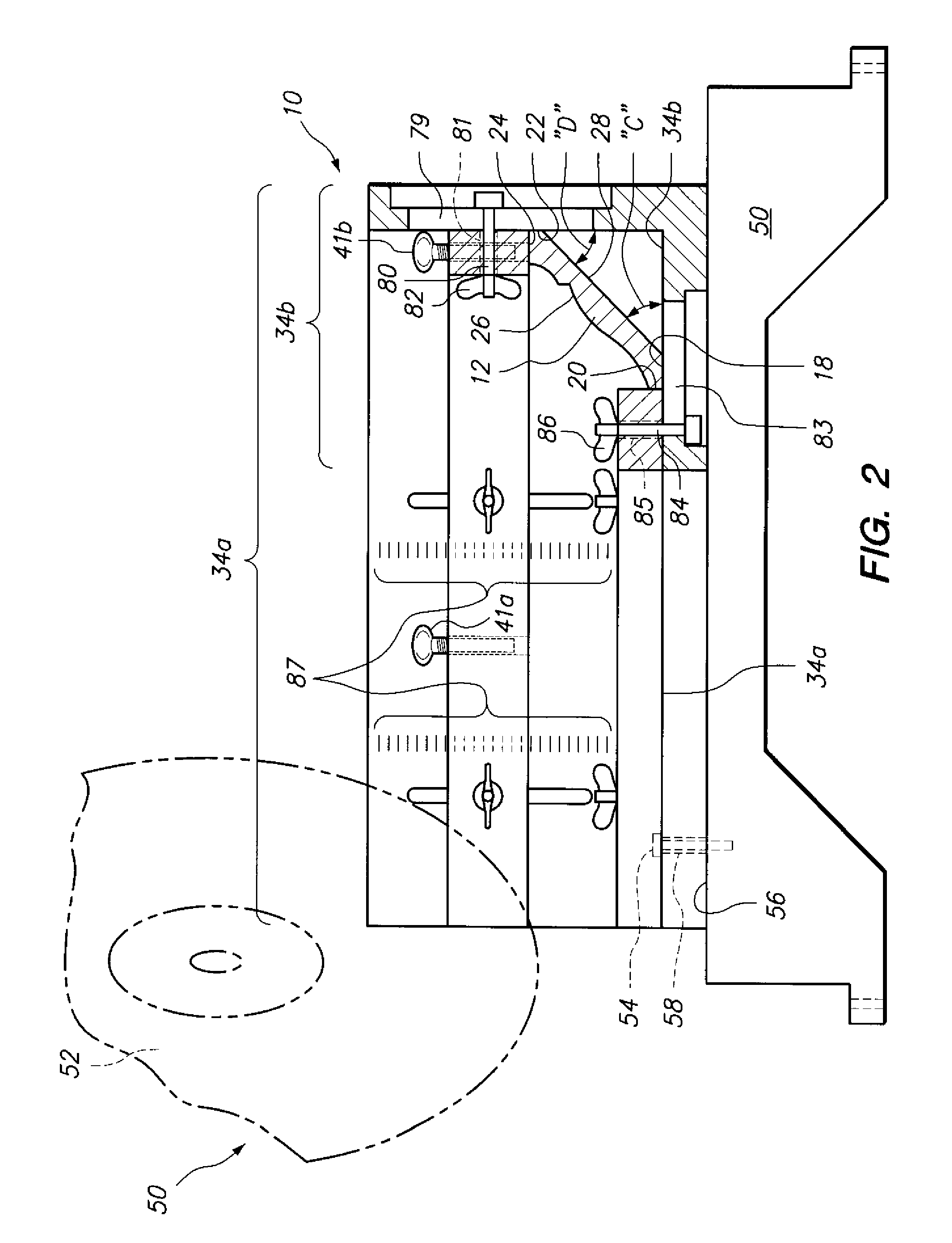
[0030]As stated above, the crown molding jig 10 may be utilized to form compound angle cuts on the distal end portions 44a, b of the crown moldings 12a, b such that the distal exterior edges 14a, b (see FIG. 1) of the first and second crown moldings 12a, b may be flush with each other when the first and second crown moldings 12a, b are butted up against each other. The guides 30a, b of the crown molding 10 shown in FIGS. 1 and 2 are fixed and do not pivot or rotate with respect to each other. In the crown molding jig 10 shown in FIGS. 1 and 2, the distal exterior edges 14a, b of the first and second crown moldings 12a, b are flush with each other when the first and second crown moldings 12a, b are oriented at 90° or 270° with respect to each other. As will be discussed below, in the crown molding jig 10a, the guides 30a, b may be oriented to each other at different angles such that the distal exterior edges 14a, b of the first and second crown moldings 12a, b are flush with each oth...


PUM

PropertyMeasurementUnit
Angleaaaaaaaaaa
Angleaaaaaaaaaa
Angleaaaaaaaaaa

Abstract

A crown molding jig may have a first guide and a second guide. Each of the guides may be sized and configured to receive a crown molding. A saw guide may be disposed between the first and second guides for guiding a saw blade and cutting a compound angle cut in the crown molding. A crown molding holder may have a base member for engaging the crown molding and an extension pole pivotally attached to the base member such that the crown molding holder may be wedged between the crown molding disposed at the ceiling and the floor. A door installation jig may have a U-shaped member sized and configured to receive a door and an inflatable tube for lifting the door to position adjacent a door frame.

Description

CROSS-REFERENCE TO RELATED APPLICATIONS[0001]This application claims the benefit of U.S. Prov. Pat. App. Ser. No. 60 / 923,426, filed on Apr. 13, 2007, the entire contents of which are incorporated herein by reference.STATEMENT RE: FEDERALLY SPONSORED RESEARCH / DEVELOPMENT[0002]Not ApplicableBACKGROUND[0003]The present invention relates to a crown molding jig, a crown molding bolder and a door installation tool.[0004]Crown molding is typically installed in a room about a portion of or about the entire inner periphery of the ceiling of a room. One of the difficult steps in installing the crown molding is forming the joint at the corner of the room. In particular, at the corner of the room, two crown molding pieces are joined to each other. To join the two crown molding pieces seemlessly, a compound angle cut must be made at the distal end portions of the mating crown moldings. Unfortunately, forming or cutting the compound angle such that the crown moldings seamlessly mate with each oth...

Claims


Application Information

Patent Timeline
IPC IPC(8): B26D7/02
CPCB27B27/08B27G5/02E04F21/0069Y10T83/0448Y10T83/7587
Inventor KHAN, VIKTOR
Owner KHAN VIKTOR
Why Eureka
Try Eureka