Safety shield for use with the winch wheel of a boat lift

Inactive Publication Date: 2008-10-16
SVI INT
View PDF24 Cites 0 Cited by
  • Summary
  • Abstract
  • Description
  • Claims
  • Application Information

AI Technical Summary

Benefits of technology

[0003]The invention seeks to minimize or prevent the potential for injury caused by accidenta

Problems solved by technology

Such accidental insertion can cause injury when the body part becomes pinched or scissored between the moving spokes/rim of the winch wheel and the

Method used


Image

  • Safety shield for use with the winch wheel of a boat lift
  • Safety shield for use with the winch wheel of a boat lift

Examples


Embodiment Construction

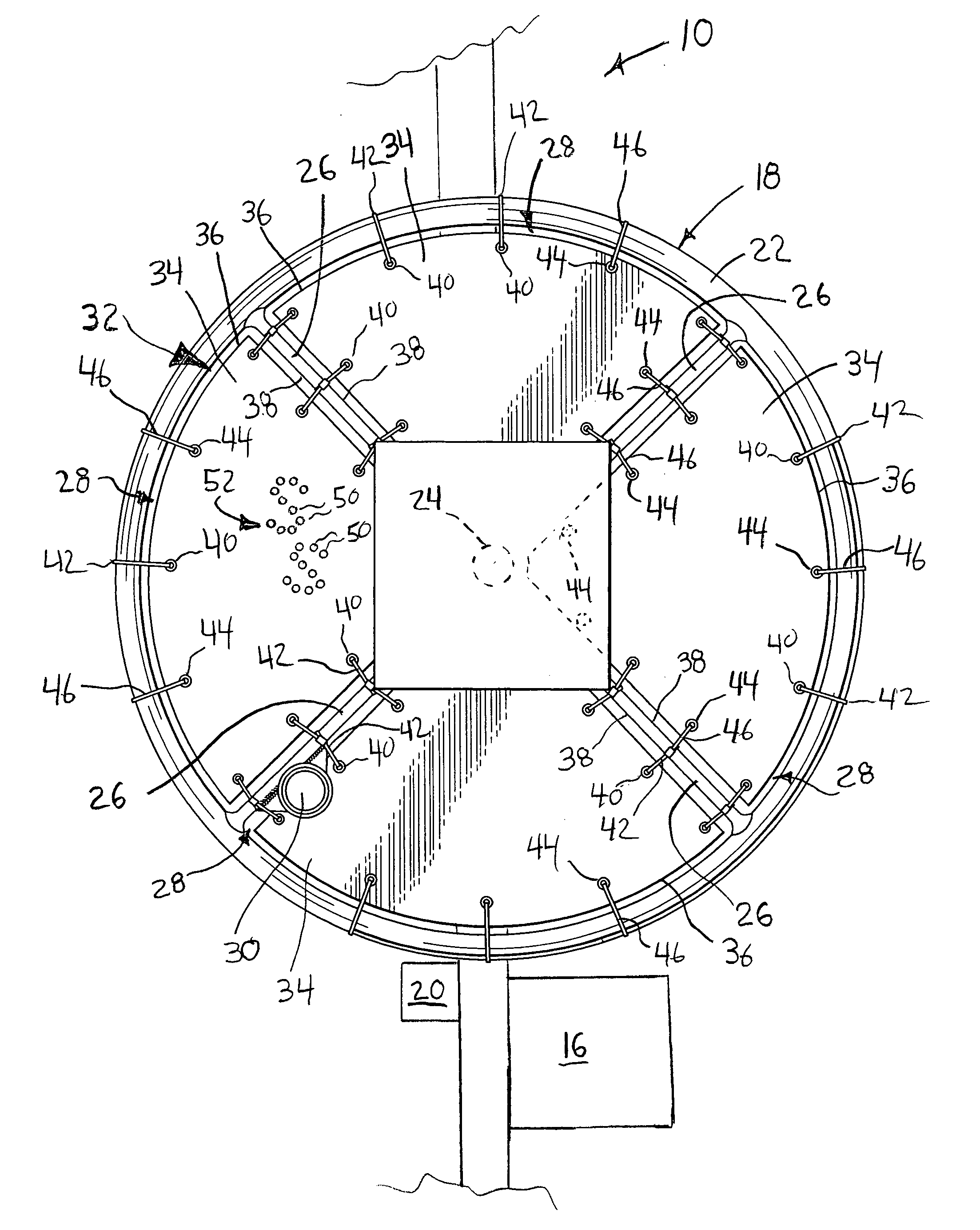
[0020]With reference to FIG. 1, a boat lift 10 is shown for raising a lowering a boat to and from a body of water. The boat lift 10 includes a lift mechanism, shown schematically at 16, that includes a manually operated winch wheel 18 for applying a drive torque to the lift mechanism 16. The lift mechanism 16 may optionally include an electric drive motor, shown schematically at 20, that can supply the drive torque to the lift mechanism 16 via the winch wheel 18 or via a direct connection to the lift mechanism 16. Because there are many know forms of boat lifts 10, lift mechanisms 16, and drive motors 20, and further because the details of these components are not critical to the invention, further description of these components will not be provided herein.

[0021]The winch wheel 18 includes a rim 22, a hub 24 connected to the remainder of the lift mechanism 16, and a plurality of spoke 26 connecting the rim 22 to the hub 24, with the rim 22 and spokes 26 defining a plurality of whee...


PUM


Abstract

A safety shield (32) is provided for use with a hand-operated winch wheel (18) of a boat lift (10), the wheel (18) having a rim (22) connected by spokes (26) to a hub (24), multiple openings (28) defined between the spokes (26) and the rim (22). The safety shield (32) includes at least one sheet of material (32) having a perimeter (36) shaped to conform to a perimeter (38) of one of the openings (28). The sheet (34) includes a plurality of connection points (40) and/or connectors (42) for attaching the perimeter (36) to the spokes (26) and the rim (22).

Description

FIELD OF THE INVENTION[0001]This invention relates to winch wheels and particularly to winch wheels used in boat lifts.BACKGROUND OF THE INVENTION[0002]It is common for boat lifts to include a manually operated winch wheel that is connected to the lift mechanism to allow a user to raise and lower a boat in the lift. Such winch wheels commonly have a rim connected by a plurality of spokes to a hub, which in turn is connected to a shaft of the lift mechanism. The rim and spokes define a plurality of openings in the wheel that are typically of a size that easily allows for the accidental insertion of a body part (finger, hand, arm, head, etc.) of a user or other person into the openings during rotation of the winch wheel. Such accidental insertion can cause injury when the body part becomes pinched or scissored between the moving spokes / rim of the winch wheel and the stationary structure of the boat lift, particularly when the winch wheel is being driven by the weight of the boat or by...

Claims


Application Information

Patent Timeline
IPC IPC(8): B65H81/06
CPCB66D1/04
Inventor CLIMENHAGA, DOUGLAS W.
Owner SVI INT
Why Eureka
Try Eureka