Method for improving the EMI performance of an LCD device

a technology of lcd device and emi performance, which is applied in the field of lcd device, can solve the problems of affecting the significant difference between the electric power consumption and the emi performance of the ppttl interface, and the distortion of image data caused by the point-to-point transmission method, so as to improve the emi performance and improve the electric power consumption of the lcd

Active Publication Date: 2008-10-16
AU OPTRONICS CORP
View PDF3 Cites 12 Cited by
  • Summary
  • Abstract
  • Description
  • Claims
  • Application Information

AI Technical Summary

Benefits of technology

[0010]The object of the present invention is to provide a method for improving the EMI performanc...

Problems solved by technology

In general, since the transistor transistor logic (TTL) interface, located between the timing controller and the source drivers of an LCD device, requires a lot of data buses to transmit image data, a serious electric power consumption and a severe Electro-Magnetic Interfering (EMI) performance are experienced at the TTL int...

Method used


Image

  • Method for improving the EMI performance of an LCD device
  • Method for improving the EMI performance of an LCD device
  • Method for improving the EMI performance of an LCD device

Examples


first embodiment

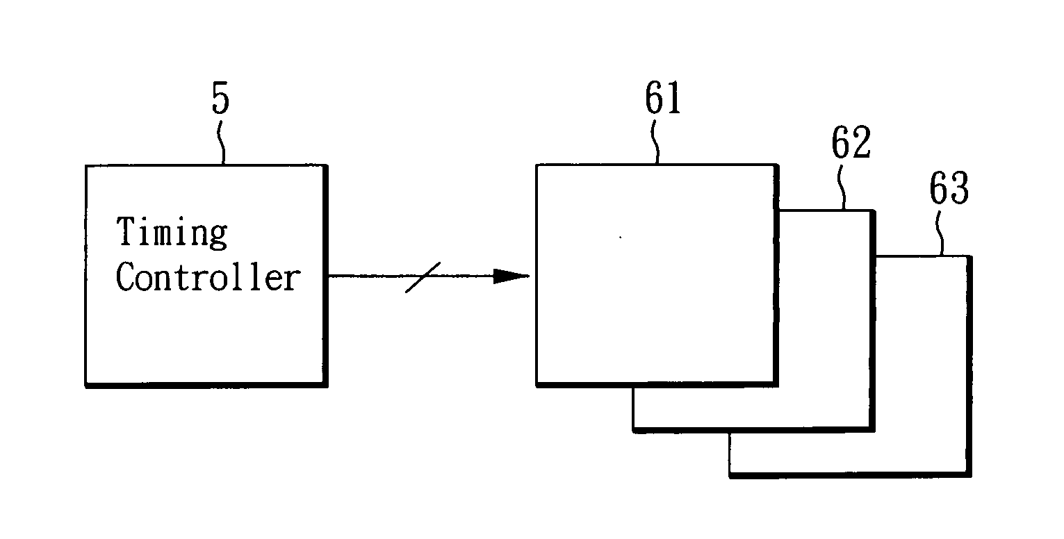
[0033]Please refer to FIG. 6, which is a timing diagram according to the present invention, along with the above description regarding FIG. 5a and FIG. 5b.

[0034]In FIG. 6, the LVDS receiving unit 57 of the timing controller 5 receives a plurality of image data, base on a plurality of CLK signals. The multi-phase CLK signal generating unit 53 transmits CLK signals 611, 612 to the plurality of source drivers 61, 62, 63. Besides, the data processing logic unit 54 transmits image data 621, 622 to the plurality of source drivers 61, 62, 63. The frequencies of the CLK signal 611 and the CLK signal 612 are smaller than the frequency of the fifth CLK signal, and the phase of the CLK signal 611 is different from the phase of the CLK signal 612. That is, the phase of the CLK signal 611 and the phase of the CLK signal 612 are different from each other, by employing the phase biasing method on the timing controller 5.

[0035]If the phase of the CLK signal 611 is same with the phase of the CLK si...

second embodiment

[0036]FIG. 7 is a timing diagram according to the present invention, and is to be referred to with the above description regarding FIG. 5a and FIG. 5b.

[0037]The operation of the second embodiment of the present invention is similar to that of the first embodiment of the present invention. The multi-phase CLK signal generating unit 53 of the timing controller 5 provides the CLK signal 611 and the CLK signal 612, while the data processing logic unit 54 transmits image data 621, 622, 623, 624 to the plurality of source drives 61, 62, 63. Besides, the phase of the image data 621 is different from the phase of the image data 623. The phase of the image data 622 is different from the phase of the image data 624.

[0038]Therefore, the timing controller 5 can transmit image data 621, 623 to the plurality of source drivers 61, 62, 63 based on the CLK signal 611, and transmit image data 622, 624 to the plurality of source drivers 61, 62, 63 based on the CLK signal 612, in order to improve the ...

third embodiment

[0039]FIG. 8 is a timing diagram according to the present invention, and is to be referred to with the above description regarding FIG. 5a and FIG. 5b.

[0040]The operation of the third embodiment of the present invention is similar to that of the first embodiment of the present invention. The multi-phase CLK signal generating unit 53 of the timing controller 5 provides a plurality of CLK signals 611, 612, 613, 614, while the data processing logic unit 54 transmits image data 621, 622, 625, 626 to the plurality of source drives 61, 62, 63. Besides, the frequencies of the plurality of CLK signals 611, 612, 613, 614 are smaller than the frequency of the fifth CLK signal. Moreover, the phase of the CLK signals 611, the phase of the CLK signals 612, the phase of the CLK signals 613, and the phase of the CLK signals 614 are different from each other.

[0041]Therefore, the timing controller 5 can transmit image data 621 to the plurality of source drivers 61, 62, 63 based on the CLK signal 61...


PUM


Abstract

A method for improving the EMI performance of an LCD device is disclosed, adapting for a point-to-point transistor transistor logic interface of the LCD device. The disclosed method comprises the following steps: receiving a plurality of image data based on a fifth CLK signal; providing a first CLK signal and a second CLK signal to a plurality of source drivers by a timing controller, wherein the frequencies of the first CLK signal and the second CLK signal are smaller than the frequency of the fifth CLK signal, the phase of the first CLK signal is different from the phase of the second CLK signal; and the timing controller transmitting a plurality of first image data to the plurality of source drivers based on the first CLK signal, and the timing controller transmitting a plurality of second image data to the plurality of source drivers based on the second CLK signal.

Description

BACKGROUND OF THE INVENTION[0001]1. Field of the Invention[0002]The present invention relates to the LCD device technical field and, more particularly, to a method for improving the EMI performance of an LCD device.[0003]2. Description of Related Art[0004]In general, since the transistor transistor logic (TTL) interface, located between the timing controller and the source drivers of an LCD device, requires a lot of data buses to transmit image data, a serious electric power consumption and a severe Electro-Magnetic Interfering (EMI) performance are experienced at the TTL interface.[0005]FIG. 1 is a block diagram showing the conventional timing controller having a TTL transmission interface. In order to improve the power consumption and the EMI problem occurring between the timing controller 1 and the source driver, the timing controller shown in FIG. 1 employs a Dual Port transmission method to transmit the image data to the source drivers. If the resolution of the display gray lev...

Claims


Application Information

Patent Timeline
IPC IPC(8): G09G5/00
CPCG09G3/3666G09G5/008G09G2330/06
Inventor YI, CHIEN-YU
Owner AU OPTRONICS CORP
Why Eureka
Try Eureka