Display unit

a display unit and display technology, applied in lighting and heating equipment, instruments, high-level techniques, etc., can solve the problems of difficult to limit the emitting angle of light, decrease visibility, and people's strong tendency to feel nervous, so as to improve the front luminance, the view angle is limited, and the effect of improving the luminan

Inactive Publication Date: 2008-10-16
SONY CORP
View PDF11 Cites 18 Cited by
  • Summary
  • Abstract
  • Description
  • Claims
  • Application Information

AI Technical Summary

Benefits of technology

[0011]In the display unit according to the embodiment of the invention, the cross section of the light guiding part is the shape expanding from the incident face to the emitting face, and the side face is the reflective face. Therefore, even when the total amount of light emission is equal, the emitting angle range is narrowed, and the light concentrates in the front direction to the emitting face. Therefore, the view angle is limited, and the front luminance is improved.
[0012]According to the display unit of the embodiment of the invention, the cross section of the light guiding part is in the shape expanding from the incident face to the emitting face, and the side face is the reflective face. Therefore, the light extraction direction can be limited to limit the view angle, and the front luminance can be improved. Consequently, the invention is particularly suitable for the usage necessitating privacy security of the display content such as mobile devices.

Problems solved by technology

It is often the case that mobile devices are used in an outside place where many people gather and people develop a strong tendency to feel nervous when others might view the screen thereof.
In addition, it is inevitable to decrease the visibility, which is caused by attaching the film thereon.
Therefore, it is difficult to limit the emitting angle of the light which is diffused and reflected by the partition wall.
Thus, it is difficult to intensify the luminance in the front direction to the light extraction face (hereinafter referred to as “front luminance”).

Method used


Image

  • Display unit
  • Display unit
  • Display unit

Examples


Embodiment Construction

[0029]An embodiment of the invention will be hereinafter described in detail with reference to the drawings.

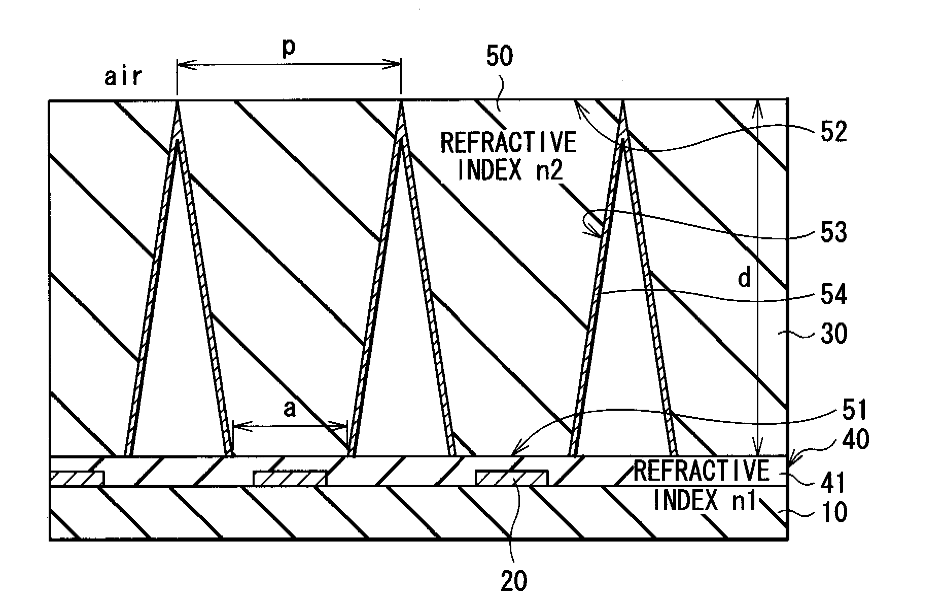
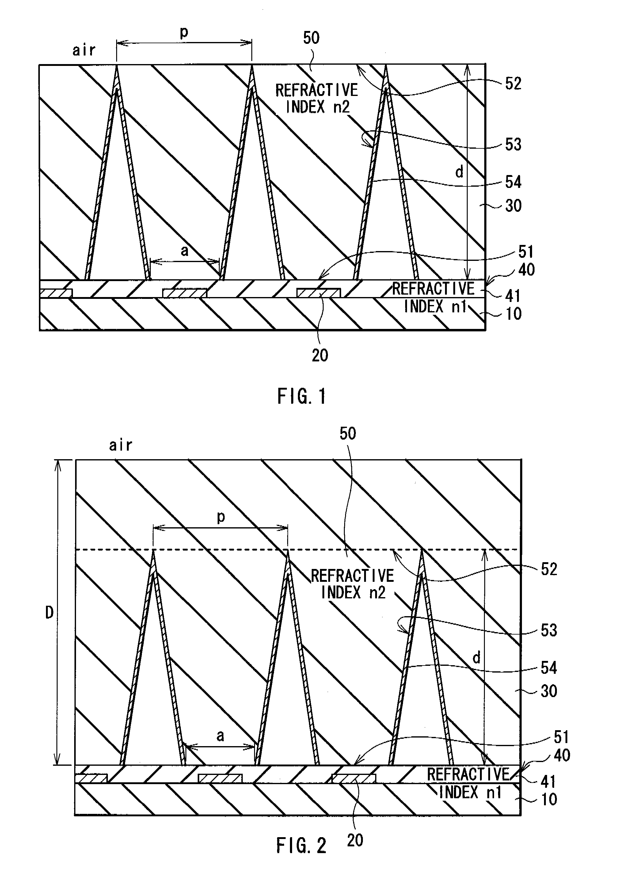
[0030]FIG. 1 shows a cross sectional configuration of a display unit according to an embodiment of the invention. The display unit is mounted on, for example, mobile devices. Display devices 20 are provided on a driving substrate 10. On the side of the driving substrate 10 where the display devices 20 are provided, a sealing substrate 30 is arranged to face the display device 20. The space between the driving substrate 10 and the sealing substrate 30 is totally filled with an intermediate layer 40.

[0031]The driving substrate 10 is made of, for example, an insulating material such as glass.

[0032]The display device 20 may be, for example, a self light emitting device such as EL (organic light emitting device) and PDP, or may be a liquid crystal device including a liquid crystal layer and a backlight.

[0033]The sealing substrate 30 seals the display devices 20 together with the in...


PUM


Abstract

A display unit which the view angle is limited and the front luminance is improved is provided. The display unit includes a display device, and a light guiding part which is provided to face the display device, has an incident face on the side opposing to the display device, an emitting face on the opposite side of the display device, and a reflective face on the side face, and has a cross section expanding from the incident face to the emitting face.

Description

CROSS REFERENCES TO RELATED APPLICATIONS[0001]The present invention contains subject matter related to Japanese Patent Application JP 2006-067550 filed in the Japanese Patent Office on Mar. 13, 2006, the entire contents of which being incorporated herein by reference.BACKGROUND OF THE INVENTION[0002]1. Field of the Invention[0003]The present invention relates to a display unit suitable for mobile devices.[0004]2. Description of the Related Art[0005]For the display mounted on the mobile devices, it is necessary that high quality images with high visibility are displayed while the battery duration is maintained as long as possible. However, the two necessities are generally conflicting. That is, to improve visibility, the luminance needs to be improved. However, the improved luminance leads to increase in the electrical power consumption. When the electrical power consumption is increased, the battery duration becomes short. Otherwise, to realize long operation of the battery, the wei...

Claims


Application Information

Patent Timeline
Patent Type & Authority Applications(United States)
IPC IPC(8): F21V8/00
CPCG02B6/0018G02B17/006H04W52/027H04M1/22G02F1/133504Y02D30/70H05B33/22
Inventor URABE, TETSUOIWASE, YUICHITSUKIHARA, KOICHITOMO, YOICHIFUKUDA, TOSHIHIRO
Owner SONY CORP
Why Eureka
Try Eureka