Optical filter and plasma display device having the same

a technology of optical filter and plasma display device, which is applied in the direction of optical elements, polarising elements, instruments, etc., can solve the problems of degrading image quality, electronic devices may malfunction, and human body damage, so as to reduce regions, limit viewing angles, and high transmittance

Inactive Publication Date: 2010-01-07
SAMSUNG SDI CO LTD
View PDF3 Cites 1 Cited by
  • Summary
  • Abstract
  • Description
  • Claims
  • Application Information

AI Technical Summary

Benefits of technology

[0013]In the optical filter according to certain embodiments of the present invention, the structure is formed of a material having a high transmittance, and the optical filter may reduce regions with limited viewing angles, when compared with a conventional optical filter. Further, the optical filter of the present invention has reduced luminance loss, increasing the degree of freedom in designing an electric circuit and gas partial pressure.

Problems solved by technology

However, since electromagnetic waves and strong near-infrared light are radiated from PDPs when plasma is generated by high voltage, the human body may be harmed and electronic devices may malfunction due to the electromagnetic waves.
Further, color purity is affected by near-infrared light, and therefore image quality may be degraded.

Method used


Image

  • Optical filter and plasma display device having the same
  • Optical filter and plasma display device having the same
  • Optical filter and plasma display device having the same

Examples


Embodiment Construction

[0020]In the following detailed description, certain exemplary embodiments of the present invention are shown and described by way of illustration. As those skilled in the art would realize, the described embodiments may be modified in various different ways, all without departing from the spirit or scope of the present invention. Accordingly, the drawings and description are to be regarded as illustrative in nature and not restrictive. In addition, when an element is referred to as being “on” another element, it may be directly on the other element, or be indirectly on the other element, with one or more intervening elements interposed therebetween. Also, when an element is referred to as being “connected to” another element, it may be directly connected to the other element, or may alternatively be indirectly connected to the other element with one or more intervening elements interposed therebetween. Hereinafter, like reference numerals refer to like elements.

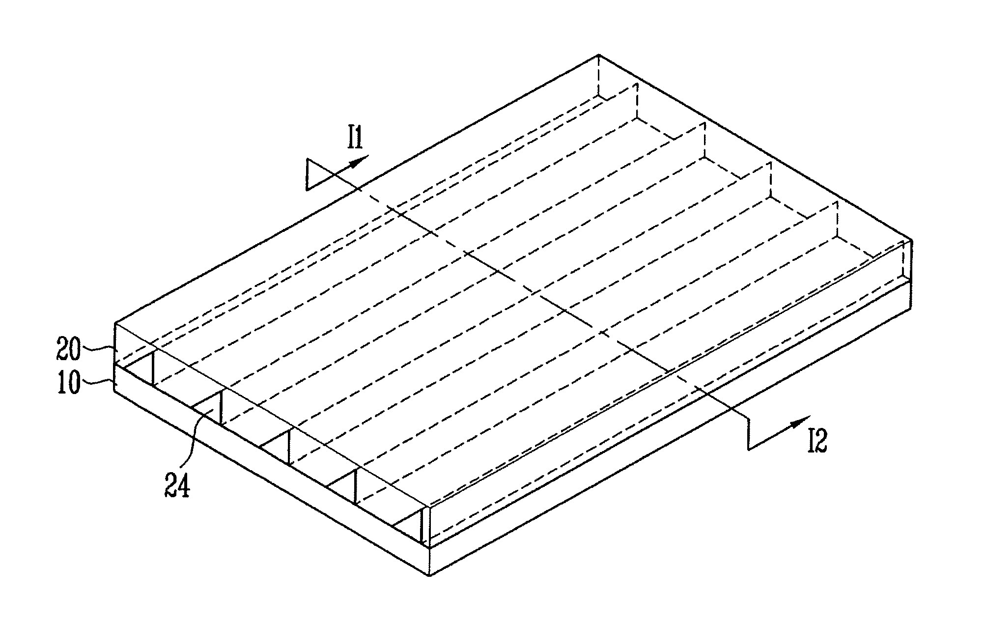
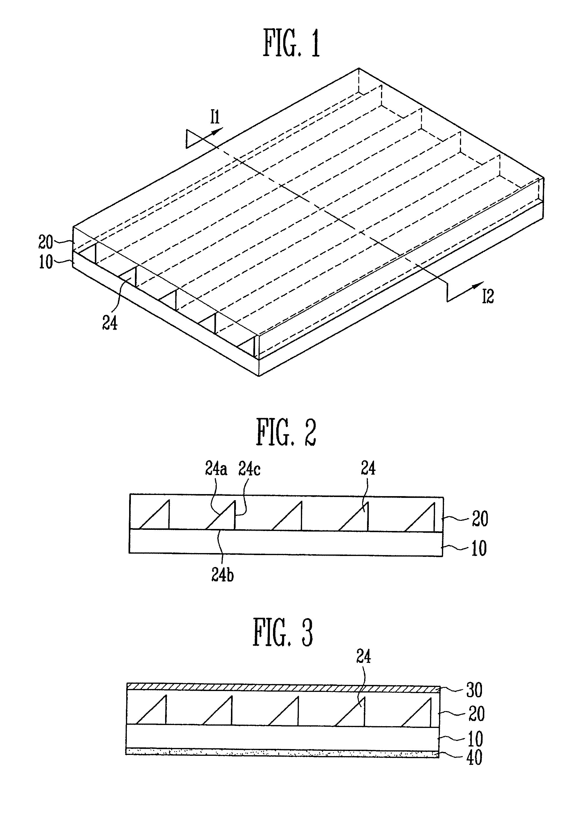
[0021]FIG. 1 is a pe...


PUM


Abstract

An optical filter and a plasma display device including the same are provided. The optical filter includes a support layer, and a plurality of stripe-shaped structures arranged at predetermined intervals on one surface of the support layer and formed using a material having a different refractive index than a refractive index of the support layer. In the optical filter, incident light is reflected at an interface between the support layer and the structure due to a difference of the respective refractive indices. Since the direction of entry of external light is the same as the reflected exit direction of the external light, visibility degradation caused by interference from the external light is minimized or reduced. Since the structure is formed using a material having a high transmittance, luminance loss of light generated by the display is also minimized.

Description

CROSS-REFERENCE TO RELATED APPLICATIONS[0001]This application claims priority to and the benefit of Korean Patent Application No. 10-2008-0063363, filed on Jul. 1, 2008, in the Korean Intellectual Property Office, the entire content of which is incorporated herein by reference.BACKGROUND[0002]1. Field of the Invention[0003]An embodiment of the present invention relates to an optical filter applied to a flat panel display device such as a plasma display device, and a plasma display device having the same.[0004]2. Description of Related Art[0005]A plasma display panel (PDP) is a flat panel display device that displays texts or images by allowing fluorescent materials to emit light using plasma generated from gas discharge. PDPs reproduce natural colors and have a relatively fast driving speed, and have larger display area and are thinner in depth than cathode ray tubes (CRTs). Therefore, PDPs have come into the spotlight as a next-generation display device.[0006]However, since electro...

Claims


Application Information

Patent Timeline
Patent Type & Authority Applications(United States)
IPC IPC(8): G02B5/28G02B1/10
CPCG02B5/136G02B17/006H01J2211/444H01J11/44H01J11/12G02B5/30
Inventor HWANG, CHA-WONKWON, DO-HYUKLEE, SANG-MIBAEK, SEUNG-GOO
Owner SAMSUNG SDI CO LTD
Why Eureka
Try Eureka