
Shoe

a technology for shoes and soles, applied in the field of shoes, can solve the problems of not being designed to account for the actual location of the heel of a person, the soles and midsoles of the prior art shoes are not designed to account for the actual location of the toe area, and the transfer of load between, etc., to achieve the effect of facilitating the flexing of the shoe, and reducing the pronation ra

Inactive Publication Date: 2012-08-16
SKECHERS US II
View PDF6 Cites 41 Cited by
  • Summary
  • Abstract
  • Description
  • Claims
  • Application Information

AI Technical Summary

Benefits of technology

"The present invention is a shoe that helps to move naturally in tandem with the motion of the foot. It achieves this by tilting the sole member gradually from the medial side of the forefoot region to the lateral side of the heel region, creating a unique curved shape that matches the natural motion of the foot. This curved shape, along with the non-uniform thickness of the sole member, allows the shoe to guide the user's foot and control its speed and motion. The front tip and rear tip of the shoe are located close to the user's toes and heel, respectively, to provide a comfortable and efficient shoe for walking, running, and other activities."

Problems solved by technology

However, none of these prior art shoes are designed to account for the actual location on a person's heel that initially bears the load incurred when a person's heel first begins to make contact with the ground at the beginning of a step.
Similarly, none of the prior art shoes are designed to account for the actual location in a person's toe area that bears the load incurred when a person's foot begins to leave the ground at the end of a step.
The soles and midsoles of the prior art shoes, however, are not designed to account for these actual load bearing locations or the transfer of the load between them.
However, due to the shape of the entire midsole in prior art shoes, the heel cleft cannot effectively enable natural motion due to the entire shoe being flat.
Prior art shoes have not accounted for the natural movement of the foot from the lateral portion of the heel region during heel-strike to the medial region of the forefoot area during toe-off.

Method used


Image

  • Shoe
  • Shoe
  • Shoe

Examples


Embodiment Construction

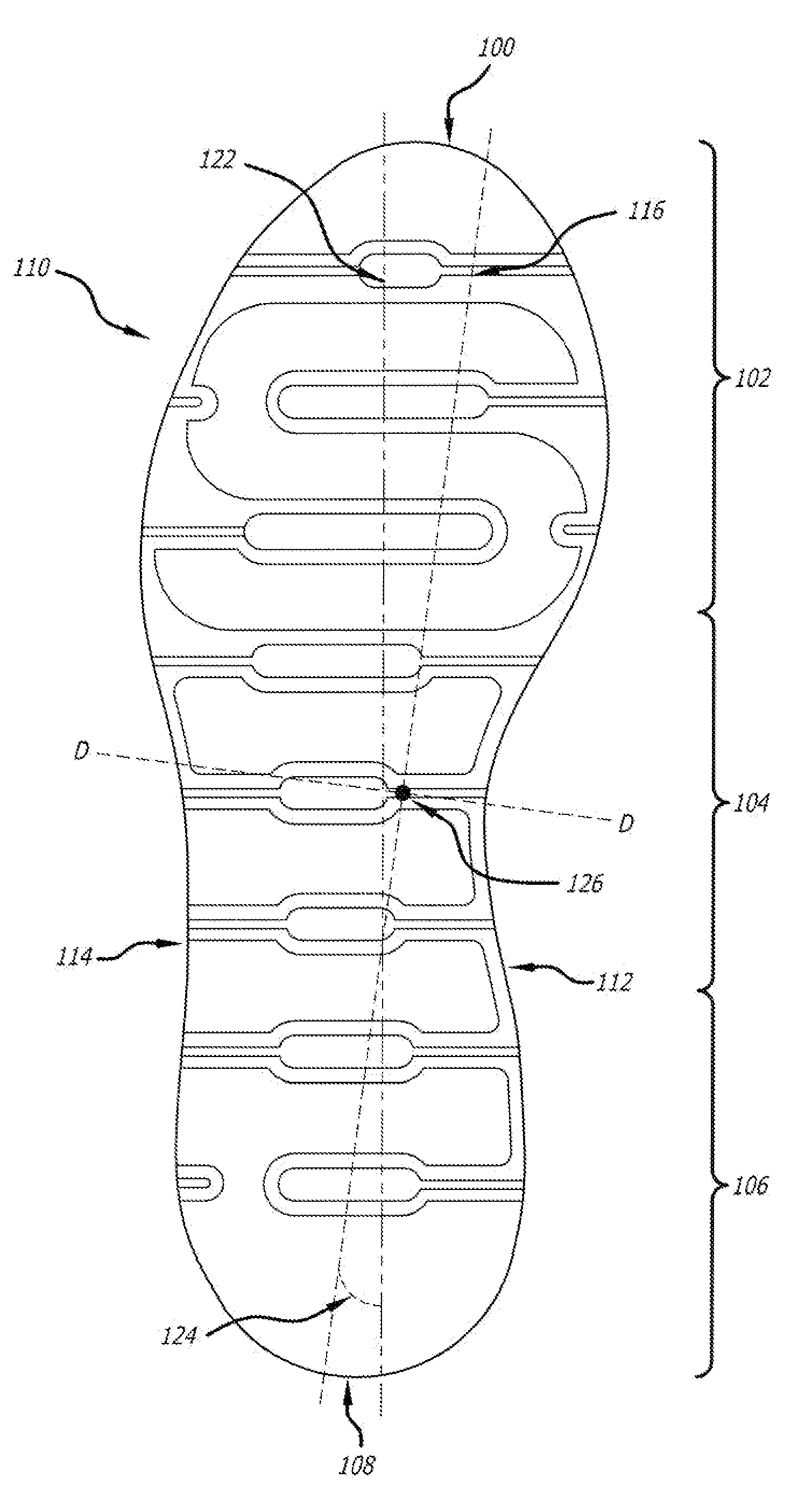
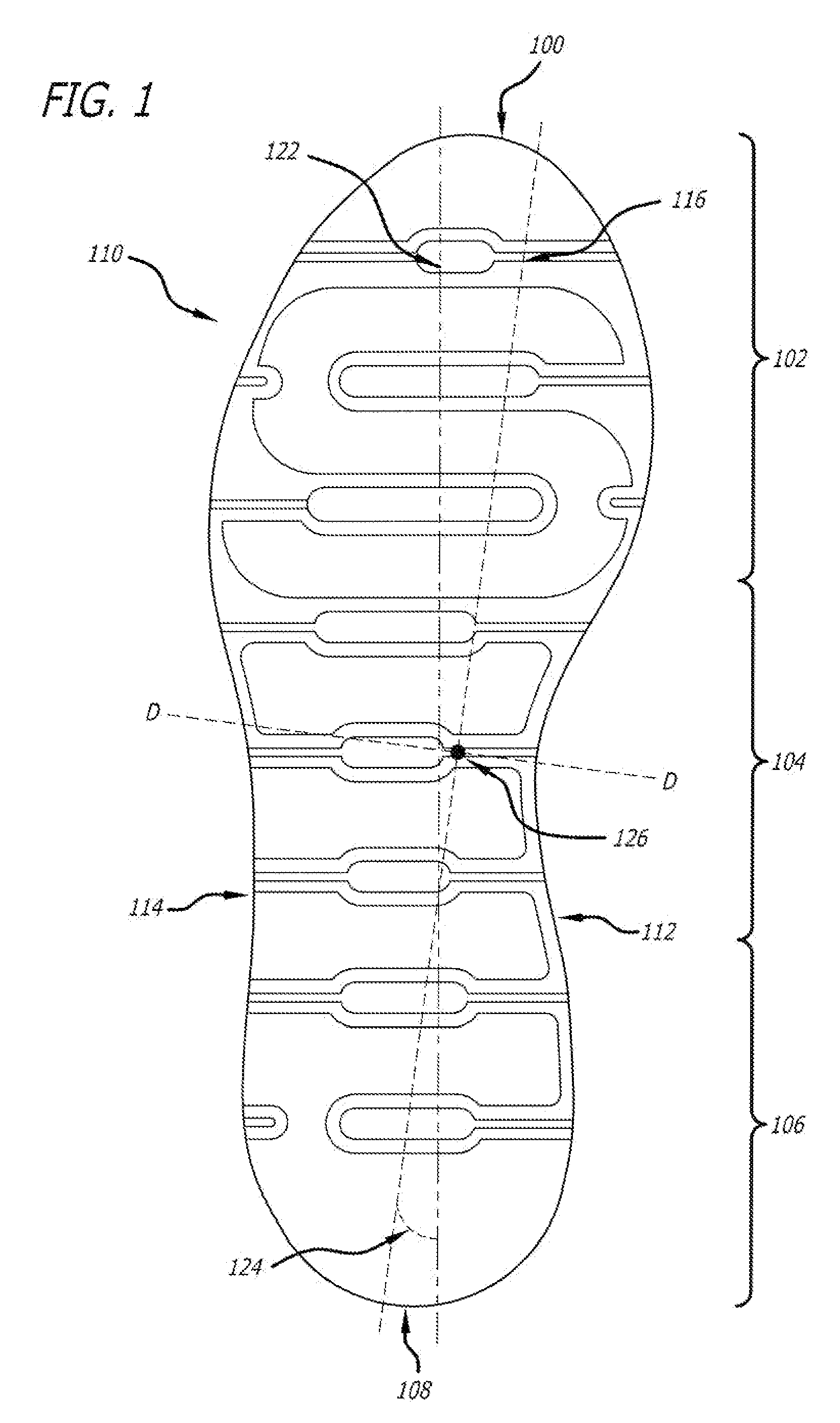
[0056]The invention will now be described with reference to the preferred embodiment shown in FIG. 1. FIG. 1 is a bottom plan view of an embodiment of the sole member 110 of a right shoe. The preferred embodiment of the shoe is comprised of an upper (not shown), a midsole and an outsole. In this preferred embodiment, the midsole and outsole are integrated and form a unitary piece, thus it is referred to as a sole member 110. A sole member may also alternatively be comprised of a combined separate outsole and separate midsole.

[0057]The sole member 110 has a front tip 100 that is located at the farthest forward point of the shoe when moving from the heel region 106 to the forefoot region 102. The shoe has a rear tip 108 that is located at the farthest rearward point of the shoe when moving from the forefoot region 102 to the heel region 106. In the preferred embodiment, the front tip 100 coincides with the frontmost point of the sole member 110 while the rear tip 108 coincides with th...


PUM


Abstract

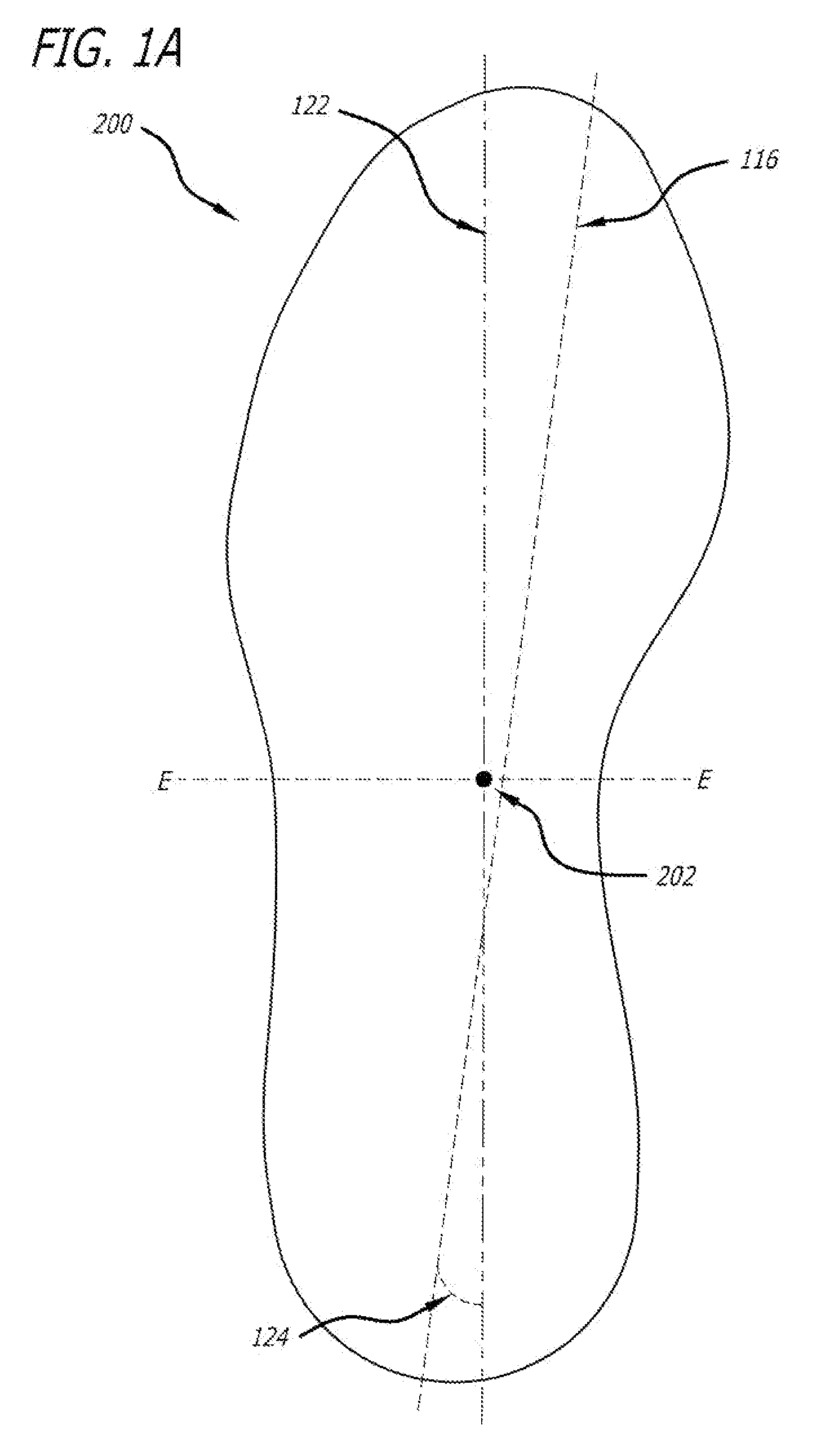
A shoe having an upper and a curved sole member, the sole member may be comprised of one unitary piece or a separate midsole and a separate outsole. The curvature results from the sole member tilting along a center of mass axis that extends through a point in the vicinity of the lateral side of the heel region of the sole member to a point in the vicinity of the medial side of forefoot region of the sole member. The center of mass axis runs diagonally along the entire length of the shoe. Due to the curvature, the sole member has a non-uniform thickness. The curvature of the sole member allows the user's foot to be guided in a more natural motion providing more movement efficiency and comfort.

Description

BACKGROUND OF THE INVENTION[0001]1. Field of the Invention[0002]The present invention relates to athletic shoes, in particular, a shoe that promotes the natural motion of the user's foot, thus providing movement efficiency and comfort for the user. This motion is achieved by a uniquely curved sole member.[0003]2. Description of the Related Art[0004]Shoes arc designed for many purposes—from protection on the job, to performance during athletic activity, to everyday use. Shoes have also been used to promote physical health and activity. Increasingly, shoes have been designed to allow the user to walk more naturally. Prior art shoes attempt to achieve such motion by having rocker bottoms, specialized midsoles, etc.[0005]However, none of these prior art shoes are designed to account for the actual location on a person's heel that initially bears the load incurred when a person's heel first begins to make contact with the ground at the beginning of a step. That initial load bearing locat...

Claims


Application Information

Patent Timeline
Patent Type & Authority Applications(United States)
IPC IPC(8): A43B13/14
CPCA43B5/06A43B13/04A43B13/145A43B13/141A43B13/125
Inventor STOCKBRIDGE, KURTRAYSSE, DAVIDCHEN, KEVIN
Owner SKECHERS US II
Learn More