Ionizer for vapor analysis decoupling the ionization region from the analyzer

Active Publication Date: 2010-07-15
SOC EURO DE ANALISIS DIFERENCIAL DE MOVILIDAD
View PDF7 Cites 41 Cited by
  • Summary
  • Abstract
  • Description
  • Claims
  • Application Information

AI Technical Summary

Benefits of technology

[0046]This invention contributes a new more efficient way of ionizing vapor species for subsequent analysis in instruments, including those using counterflow gas. The approach is particularly advantageous in situations where the available vapor sample is limited. Dilution of target ions as they cross the counterflow region is reduced. Thus the sensitivity of the system ‘ionizer plus analyzer’ will be increased independently of whether the vapor sample is limited or not. Sample dilution and loss of useful ionization volume associated to the counterflow jet are virtually eliminated by performing the functions of the ionizer and the counterflow gas in two different chambers. The sample vapors first enter into an ionization chamber where they mix with the charging ions or drops, producing a certain concentration n, of ionized vapors near the exit of the chamber. The bottom of the ionization chamber communicates through an exit orifice with an impaction chamber located below it. A jet of sample flow leaves the ionization chamber through said exit orifice, and impacts frontally against the counterflow jet originating from the bottom

Problems solved by technology

Hence, this desired target ion flux is relatively independent of the sample flow rate which can be r

Method used


Image

  • Ionizer for vapor analysis decoupling the ionization region from the analyzer
  • Ionizer for vapor analysis decoupling the ionization region from the analyzer
  • Ionizer for vapor analysis decoupling the ionization region from the analyzer

Examples


Embodiment Construction

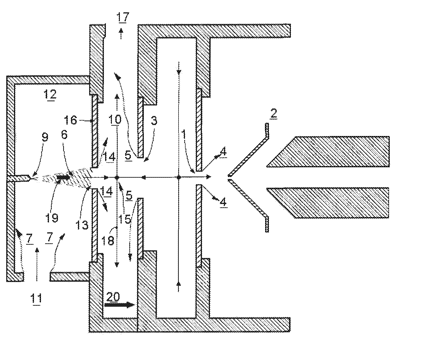
[0056]The new ionizer isolates the effective ionization volume from the counterflow region by placing them in separate chambers: an ionization chamber and an impaction chamber. Both chambers are communicated through an orifice, to be referred to as the impaction orifice. The impaction orifice is formed in the plate separating both chambers (the impaction plate), and is approximately aligned with the axis of the inlet orifice (1) to the analytical instrument (2), as shown in FIG. 3. The analytical instrument (2) may be, for instance, a mass spectrometer or a differential mobility analyzer. The counterflow jet (5) emerges from the curtain plate orifice (3) and enters the counterflow impaction chamber (10). The sample flow (7) enters first through the sample inlet (11) in the ionization chamber (12), where it gets in contact with the electrospray cloud (6). In the impaction orifice (13), the sample flow is accelerated towards the counterflow impaction chamber (10). The jet formed by th...


PUM


Abstract

A method and apparatus are described to increase the efficiency with which a sample vapor is ionized prior to being introduced into an analyzer. Excellent contact between the vapor and the charging agent is achieved in the ionization chamber by separating it from the analyzer by means of a perforated impaction plate. As a result, some desired fraction of the gas going into the analyzer or coming out of the analyzer can be controlled independently from the flow of sample through the ionization chamber. Furthermore, penetration into said ionization chamber of said desired fraction of the gas going into or out of the analyzer is minimized by controlling the dimensions of said perforated impaction plate. Ions formed in the ionization chamber are driven partly by electric fields through said hole in said perforated impaction plate into the inlet to the analyzer. As a result, most of the gas sampled into the analyzer carries ionized vapors, even when the sample flow of vapor is very small, and even when the analyzer uses counterflow gas.

Description

CROSS REFERENCE TO RELATED APPLICATION[0001]This application claims the benefit of priority to U.S. Provisional Patent Application No. 61 / 204,996, filed January 14, 2009, the entire contents of which is incorporated by reference herein.U.S. PATENTS AND APPLICATIONS CITED[0002]U.S. Pat. No. 4,300,044; Iribarne; Julio V., Thomson; Bruce A, Method and apparatus for the analysis of chemical compounds in aqueous solution by mass spectroscopy of evaporating ions, Filed: May 7, 1980.[0003]U.S. Pat. No. 4,531,056 ; Michael J. Labowsky, John B. Fenn, Masamichi Yamashita ; Method and apparatus for the mass spectrometric analysis of solutions; Apr. 20, 1983.[0004]U.S. Pat. No. 4,963,736; Donald J. Douglas, John B. French; Mass spectrometer and method and improved ion transmission; Nov. 15, 1989.[0005]U.S. Pat. No. 6,107,628; Keqi Tang, Mikhail B. Belov, Aleksey V. Tolmachev, Harold R. Udseth, Richard D. Smith; Multi-source ion funnel; Mar 25, 2003.[0006]U.S. patent application Ser. No. 11 / 732,...

Claims


Application Information

Patent Timeline
IPC IPC(8): H01J27/20H01J49/26H01J49/10H01T19/00
CPCH01J49/10H01J49/0422H01J49/145
Inventor VIDAL-DE-MIGUEL, GUILLERMO
Owner SOC EURO DE ANALISIS DIFERENCIAL DE MOVILIDAD
Why Eureka
Try Eureka