Method for producing organic electroluminescent display panel

a technology of electroluminescent display panels and electroluminescent light, which is applied in the direction of basic electric elements, electrical equipment, semiconductor devices, etc., can solve problems such as display quality degradation, and achieve the effects of improving production efficiency, preventing color mixture, and improving display quality

Active Publication Date: 2017-02-02
SHARP KK
View PDF1 Cites 0 Cited by
  • Summary
  • Abstract
  • Description
  • Claims
  • Application Information

AI Technical Summary

Benefits of technology

[0025]The present invention can provide a method for producing an organic EL display panel which can prevent color mixture, improve the display quality, and improve the production efficiency.

Problems solved by technology

This vapor deposition technique, however, may cause disadvantages of color mixture between adjacent pixels and deterioration of the display quality.

Method used


Image

  • Method for producing organic electroluminescent display panel
  • Method for producing organic electroluminescent display panel
  • Method for producing organic electroluminescent display panel

Examples


embodiment 1

[0036 describes the case of performing the vapor deposition and the etching treatment for the luminescent material of each luminescent color in the same chamber.

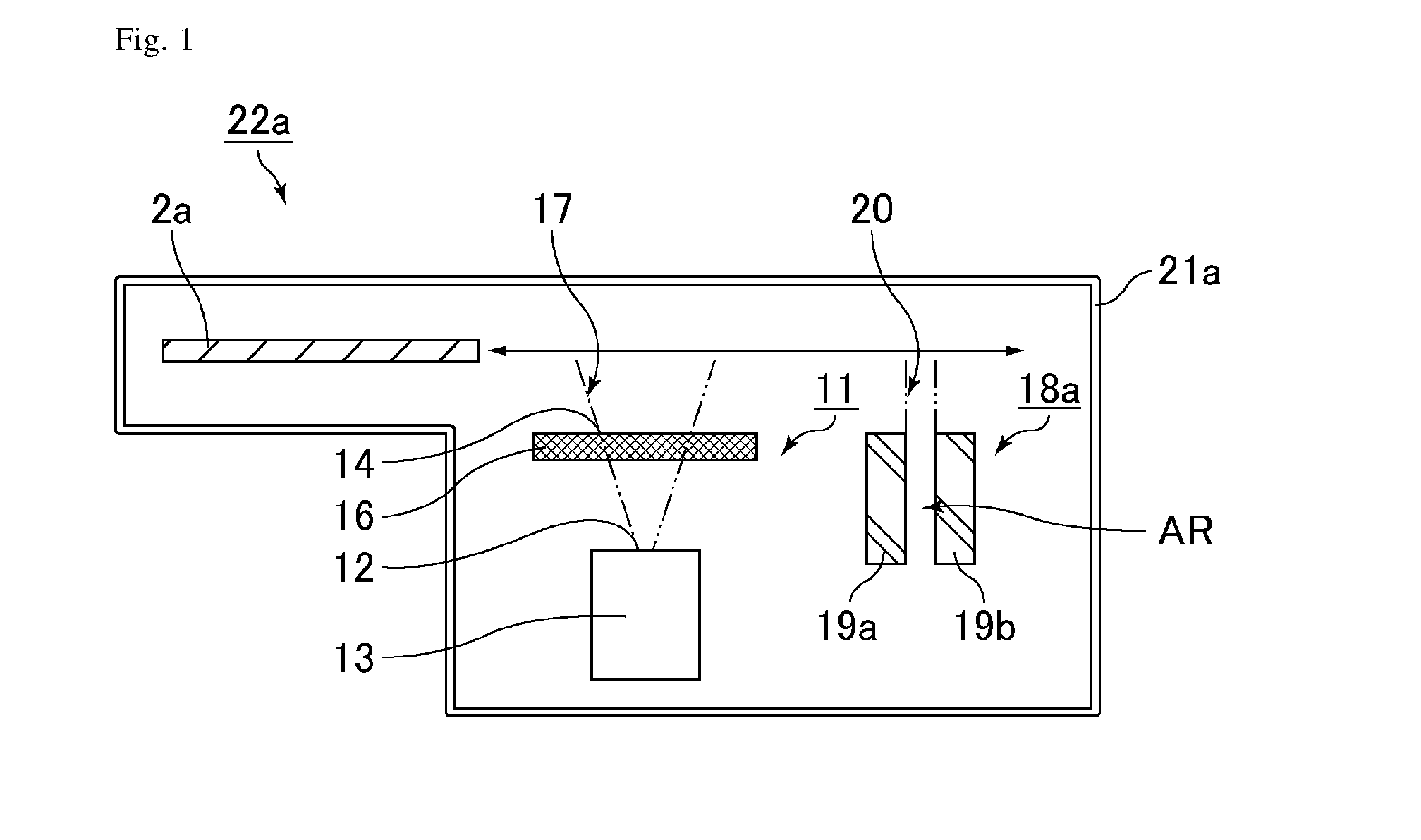
[0037]First, the configuration of an apparatus unit used in the step of forming light-emitting layers is described with reference to FIG. 1. FIG. 1 is a schematic cross-sectional view illustrating an apparatus unit used in the step of forming light-emitting layers in production of an organic EL display panel of Embodiment 1. As illustrated in FIG. 1, an apparatus unit 22a used in the step of forming light-emitting layers includes a vapor deposition apparatus 11 and a plasma treatment apparatus 18a. The vapor deposition apparatus 11 and the plasma treatment apparatus 18a are disposed, in the given order, in a chamber 21a.

[0038]The vapor deposition apparatus 11 includes a vapor deposition source 13 provided with nozzles 12 configured to eject vapor deposition particles, and a mask 16 provided with openings 14. A limiting plat...

embodiment 2

[0057]FIG. 3 is a schematic cross-sectional view illustrating an apparatus unit used in the step of forming light-emitting layers in production of an organic EL display panel of As illustrated in FIG. 3, an apparatus unit 22b used in the step of forming light-emitting layers includes the vapor deposition apparatus 11 and the plasma treatment apparatus 18a. The vapor deposition apparatus 11 and the plasma treatment apparatus 18a are disposed respectively in chambers 21b and 21c. The chambers 21b and 21c are divided by a shutter (not illustrated), for example, so that the apparatus unit 22b can move the target substrate 2a between the chambers 21b and 21c without allowing the substrate to be out of the chambers. By performing the respective treatments (vapor deposition and etching) while moving the target substrate 2a in the directions of the arrow in the apparatus unit 22b, light-emitting layers are formed. There are three apparatus units 22b for the respective luminescent colors. S...

embodiment 3

[0062]FIG. 4 is a schematic cross-sectional view illustrating an apparatus unit used in the steps (steps a to c) of forming light-emitting layers in production of an organic EL display panel of First, the treatment is performed using an apparatus unit 22c as illustrated in the step (a) of FIG. 4. The apparatus unit 22c includes, in a chamber 21d, a vapor deposition apparatus 11R for the luminescent material of the luminescent color R. In such an apparatus unit 22c, the luminescent material of the luminescent color R is vapor-deposited by the vapor deposition apparatus 11R while a target substrate 2b is moved in the directions of the arrow.

[0063]Next, treatments are performed using an apparatus unit 22d as illustrated in the step (b) of FIG. 4. The apparatus unit 22d includes in the given order, in a chamber 21e, a plasma treatment apparatus 18R for the luminescent material of the luminescent color R and a vapor deposition apparatus 11G for the luminescent material of the luminescen...


PUM

PropertyMeasurementUnit
thicknessaaaaaaaaaa
thicknessaaaaaaaaaa
frequencyaaaaaaaaaa

Abstract

The method for producing an organic EL display panel includes, in the given order, the steps of: forming a first light-emitting layer by forming a film from a luminescent material of a first luminescent color in a first pixel; performing the etching treatment to remove, while leaving the first light-emitting layer to remain, a thin film of the luminescent material of the first luminescent color which adhered to the second pixel in the step; forming a second light-emitting layer by forming a film from a luminescent material of a second luminescent color different from the first luminescent color in the second pixel; and performing the etching treatment to remove, while leaving the second light-emitting layer to remain, a thin film of the luminescent material of the second luminescent color which adhered to the first pixel in the step.

Description

CROSS-REFERENCE TO RELATED APPLICATIONS[0001]This application is a U.S. National Phase patent application of International Patent Application No. PCT / JP2014 / 074474, filed on Sep. 17, 2014, which claims priority to Japanese Application No. 2013-251276, filed on Dec. 4, 2013, each of which is hereby incorporated by reference in the present disclosure in its entirety.FIELD OF THE INVENTION[0002]The present invention relates to methods for producing organic electroluminescent display panels (hereinafter, also referred to as “organic EL display panels”). The present invention more specifically relates to a method for producing an organic EL display panel including light-emitting layers wherein the luminescent colors of adjacent light-emitting layers are different from each other.BACKGROUND OF THE INVENTION[0003]Organic electroluminescent elements (hereinafter, also referred to as “organic EL elements”) utilizing electroluminescence of organic materials have drawn attention as display ele...

Claims


Application Information

Patent Timeline
Patent Type & Authority Applications(United States)
IPC IPC(8): H01L51/56H01L27/32H01L51/00
CPCH01L51/56H01L51/5012H01L27/3211H01L51/0017H10K59/35H10K71/231H10K71/00H10K50/11
Inventor MATSUNAGA, KAZUKIKIKUCHI, KATSUHIROKAWATO, SHINICHIINOUE, SATOSHIKOBAYASHI, YUHKIOCHI, TAKASHI
Owner SHARP KK
Why Eureka
Try Eureka