Substrate for organic EL and method for manufacturing the same

a technology of organic el and substrate, which is applied in the direction of discharge tube/lamp details, discharge tube luminescnet screen, transportation and packaging, etc., can solve the problems of ineffective means of making banks, inability to develop plasma inside the vacuum chamber, and inability to achieve plasma treatment inside the vacuum chamber

Inactive Publication Date: 2006-08-03
DAINIPPON SCREEN MTG CO LTD
View PDF10 Cites 18 Cited by
  • Summary
  • Abstract
  • Description
  • Claims
  • Application Information

AI Technical Summary

Benefits of technology

[0010] The present invention has been made in light of the problems above. Accordingly, the object of the present invention is to provide a substrate for organic EL which prevents color mixing of organic EL materials between adjacent banks even on a large-size substrate while the organic EL materials are being supplied between the banks formed on the substrate, and to provide a method of manufacturing such a substrate.

Problems solved by technology

By the way, while the sizes of substrates are becoming larger for efficient manufacturing, an attempt to perform plasma treatment of a large-size substrate gives rise to the following problem.
Hence, it is difficult to develop plasma inside the vacuum chamber, due to which plasma treatment inside the vacuum chamber becomes impractical in terms of both the size and the tact of the plasma treatment.
However, there has not been any effective means of making banks formed on a large substrate liquid repellent and preventing color mixing of organic EL materials.

Method used


Image

  • Substrate for organic EL and method for manufacturing the same
  • Substrate for organic EL and method for manufacturing the same
  • Substrate for organic EL and method for manufacturing the same

Examples


first embodiment

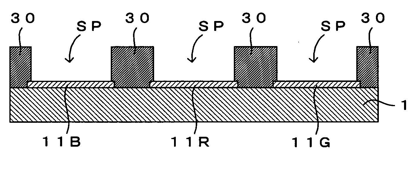
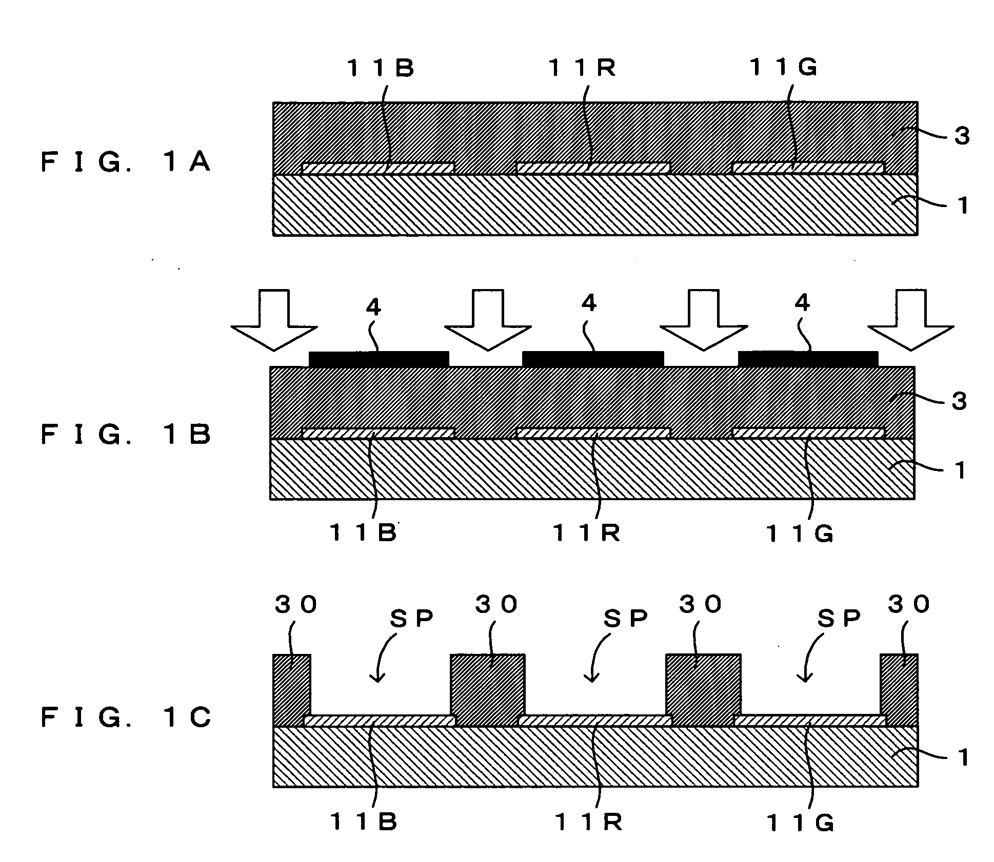
[0020]FIGS. 1A through 1C are drawings which show a first embodiment of a method of manufacturing a substrate for organic EL of the invention. In this embodiment, first, by a coating method such as spin coating, an oil repellent photosensitive material which will become a bank (barrier wall) material which will be described later is applied upon a substrate 1 which first electrodes 11R, 11G and 11B are formed by patterning on the surface as shown in FIG. IA (coating step). This forms an oil repellent photosensitive material layer 3 on the substrate 1. The first electrodes 11R, 11G and 11B are obtained by patterning an ITO (indium tin oxide) film into plural stripes for instance, and correspond to anodes. To secure emission of light (luminescence from organic EL layers which will be described later) from the back surface (bottom surface) side of the substrate, a glass substrate, a transparent plastic substrate or the like is used as the substrate 1, and the first electrodes 11R, 11G ...

second embodiment

[0034]FIGS. 3A through 3D are drawings which show a second embodiment of the method of manufacturing a substrate for organic EL of the invention. A major difference of the second embodiment from the first embodiment is that the banks have a double-layer structure, that is, top layer parts of the banks are made of an oil repellent photosensitive material and bottom layer parts of the banks are made of a non-liquid repellent photosensitive material. The second embodiment is otherwise similar in structure and operation to the first embodiment. The difference will therefore be mainly described below.

[0035] First, as shown in FIG. 3A, the substrate 1 which the first electrodes 11R, 11G and 11B are patterned on the surface is coated with a non-oil repellent photosensitive material (first coating step). In consequence, a non-oil repellent photosensitive material layer 2 which will become bottom layer films is formed on the substrate 1. The non-oil repellent photosensitive material may be ...


PUM


Abstract

A non-oil repellent photosensitive material layer 2 and an oil repellent photosensitive material layer 3 formed by coating on a substrate 1 are exposed at the same time with light having a single wavelength (I-line) in accordance with bank regions and thereafter developed. In consequence, banks 300 are formed having a double-layer structure which is comprised of bottom layer portions 31 of a non-oil repellent material and top layer portions 32 of an oil repellent material. This blocks organic EL materials supplied between the banks 300 from moving beyond tops of the banks 300 and prevents color mixing of the organic EL materials. Further, since the bottom layer portions 31 between which organic layers are formed are made of the non-oil repellent material, the profiles of the organic layers will not change due to surface tension.

Description

CROSS REFERENCE TO RELATED APPLICATION [0001] The disclosure of Japanese Patent Application No. 2005-026209 filed Feb. 2, 2005 including specification, drawings and claims is incorporated herein by reference in its entirety. BACKGROUND OF THE INVENTION [0002] 1. Field of the Invention [0003] The present invention relates to a substrate for organic EL which is used for forming organic layers, such as hole transportation layers and organic EL (electro-luminescence) layers, in predetermined pattern shapes, and to a method of manufacturing such a substrate. [0004] 2. Description of the Relates Art [0005] A conventional organic EL element is manufactured in the following manner. First, a transparent ITO (indium tin oxide) film is deposited on a surface of a transparent substrate which may be a glass substrate. Next, the ITO film deposited on this substrate is patterned into first electrodes which are shaped like plural stripes, utilizing a photolithographic technique. The first electrode...

Claims


Application Information

Patent Timeline
Patent Type & Authority Applications(United States)
IPC IPC(8): H01J1/88
CPCH01L27/3283H01L51/0005H01L51/56Y10T428/3154H10K59/173H10K71/135H10K71/00H05B33/22H05B33/10
Inventor MASUICHI, MIKIOFUJIMOTO, YOSHIHIRO
Owner DAINIPPON SCREEN MTG CO LTD
Why Eureka
Try Eureka