

Canister
- Summary
- Abstract
- Description
- Claims
- Application Information
AI Technical Summary
Benefits of technology
Problems solved by technology
Method used
Image

Examples
Embodiment Construction
[0020]The detailed description of embodiments of a canister according to the invention will be given with reference to the accompanying drawings.
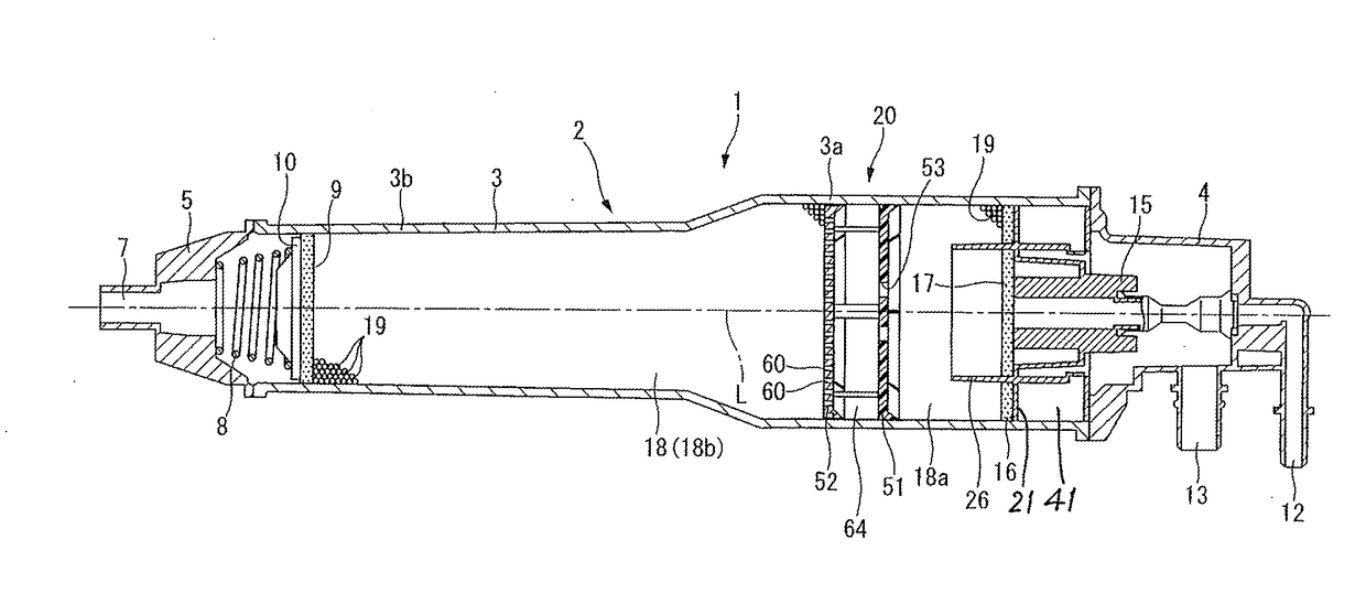
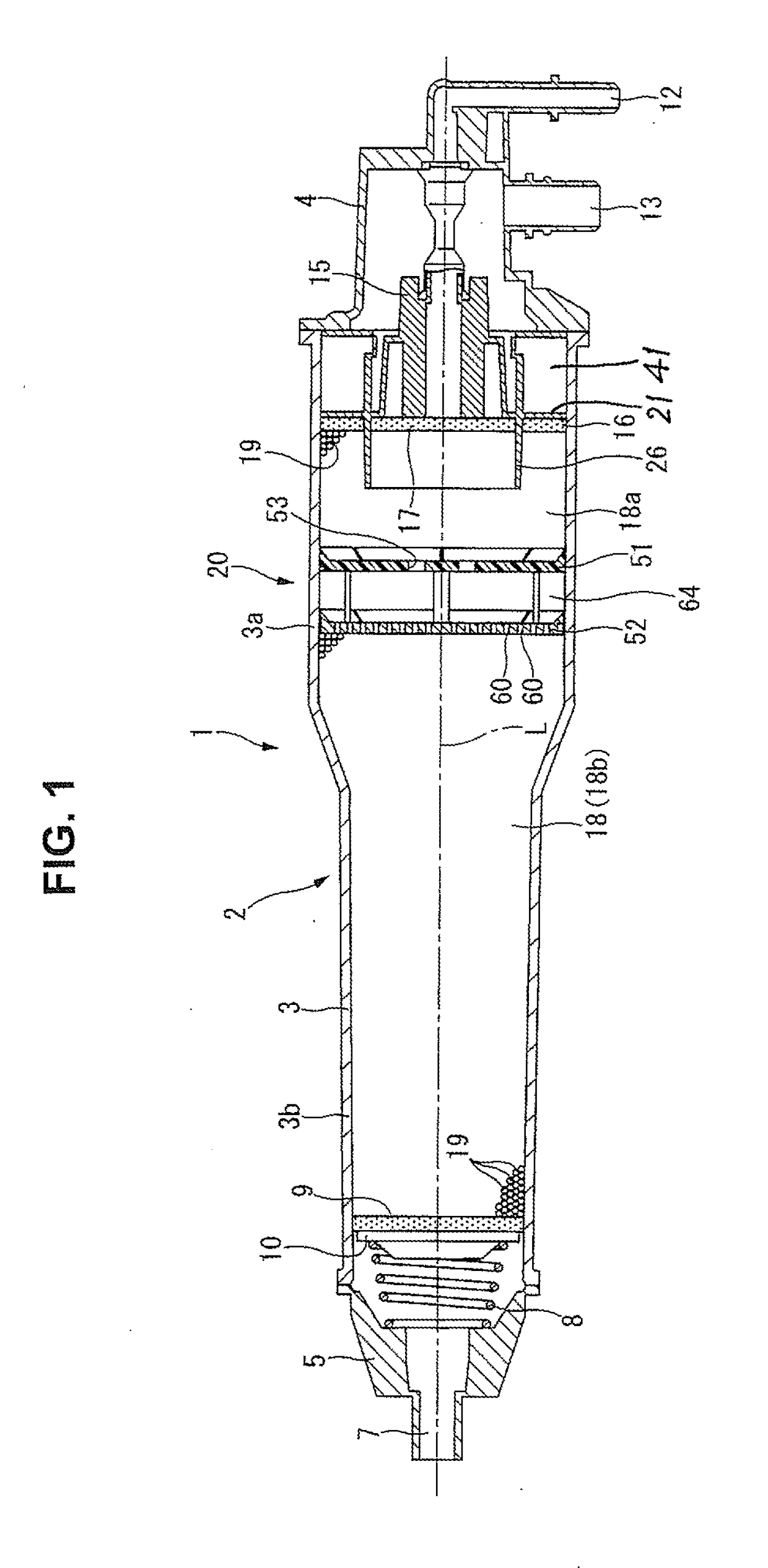
[0021]Referring now to the drawings, particularly to FIG. 1, there is shown the longitudinal cross-section of a canister of the first embodiment. Canister 1 has a synthetic-resin case 2. The case 2 is mainly constructed by a cylindrical-hollow main body (housing) 3 having a complete circular cross section, a charge / purge-side end cover 4, and a drain-side end cover 5. The main body 3 is comprised of a large-diameter part 3a and a small-diameter part 3b. Both ends of main body 3 are formed as an opening end on the side of large-diameter part 3a and an opening end on the side of small-diameter part 3b, respectively. Charge / purge-side end cover 4 is attached to the opening end of large-diameter part 3a, while drain-side end cover 5 is attached to the opening end of small-diameter part 3b.
[0022]The drain-side end cover 5 is formed at its centr...
PUM
| Property | Measurement | Unit |
|---|---|---|
| Length | aaaaa | aaaaa |
| Diameter | aaaaa | aaaaa |
| Shape | aaaaa | aaaaa |
Abstract
Description
Claims
Application Information