Tooth and Adaptor Assembly

a technology of adaptors and teeth, applied in the field of mining and construction industries, can solve the problems of extreme wear on teeth, inconvenient casting, and inability to meet the needs of use, and achieve the effects of reducing high stress regions, easy casting, and extreme difficulty in removal

Inactive Publication Date: 2008-08-28
BRADKEN OPERATIONS
View PDF20 Cites 38 Cited by
  • Summary
  • Abstract
  • Description
  • Claims
  • Application Information

AI Technical Summary

Benefits of technology

[0018]In contrast with the prior art the present invention provides a configuration which is easy to cast, reducing regions of high stress. Furthermore, the locking mechanism is fully enclosed, protecting it from the abrasive surroundings which could damage the mechanism and make removal extremely difficult.
[0019]As the locking mechanism is fully enclosed in the enclosure, there is no chance that the mechanism can be unintentionally dislodged and allow the tooth to be removed from the adaptor, to expose the adaptor to the environment. As the locking mechanism is protected, the forces required to retain the locking mechanism are greatly reduced than prior art configurations, and hence requires minimal force to remove the locking mechanism, enabling quick change out time, reducing the amount of downtime of the machinery.
[0020]Owing to the design of the present invention, the entire tooth is used as a wear protection element for the adaptor. Hence there is no additional weight added to the tooth which would not prolong its life.
[0021]Also, the shape of the tooth allows for easy casting, reducing areas of increased stress, which may cause failure of the assembly during service. This is true for the tooth but also for the adaptor. The simple shape of the nose of the adaptor represents minimal change to its cross sectional shape and allows the socket of the tooth to be manufactured such that it is snugly received on the nose.
[0042]Preferably the upper wall and bottom wall of the tooth have a curved section which protrudes beyond the sidewalls. The curved section adds further wear protection to the adaptor.

Problems solved by technology

This machinery is often used in an extremely abrasive environment resulting in extreme wear on components.
These teeth experience substantial wear and may need to be replaced daily in some environments.
However, the configurations put forward to date are not without disadvantages.
Furthermore, the pins exposure to the environment can result in damage to the pin rendering it even more difficult to dislodge.
Other configurations are complex in shape, often having large areas of metal extending beyond the main body of the tooth.
These shapes can be difficult to cast and may result in the build up of stresses within the adaptor or tooth during casting, creating weak points within the components.
Also, the extra metal does not always contribute to extending the wear life of the tooth and hence adds unnecessary weight to the assembly.
The cross section of the adaptor must therefore change significantly to accommodate these complimentary shapes, resulting in concentrations of stress during manufacture and service of the component.
This obviously weakens the structure and induces areas of stress within the component.

Method used


Image

  • Tooth and Adaptor Assembly
  • Tooth and Adaptor Assembly
  • Tooth and Adaptor Assembly

Examples


Embodiment Construction

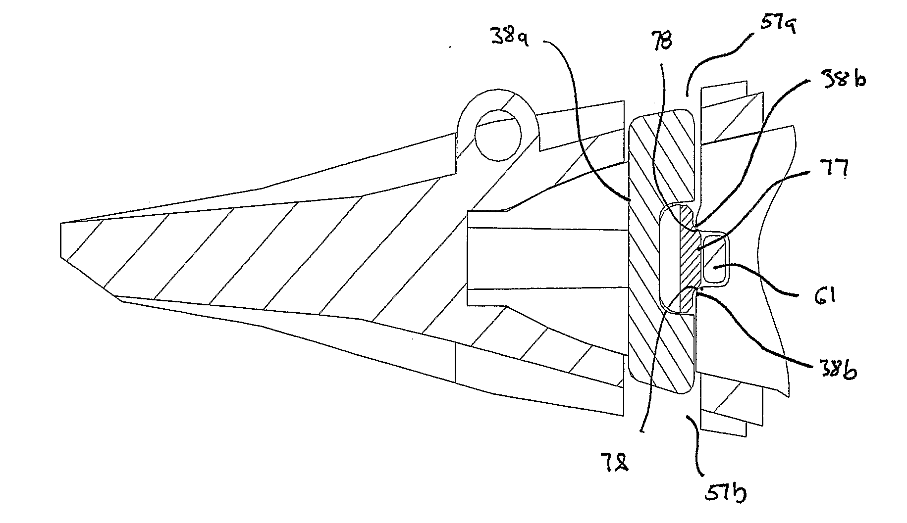
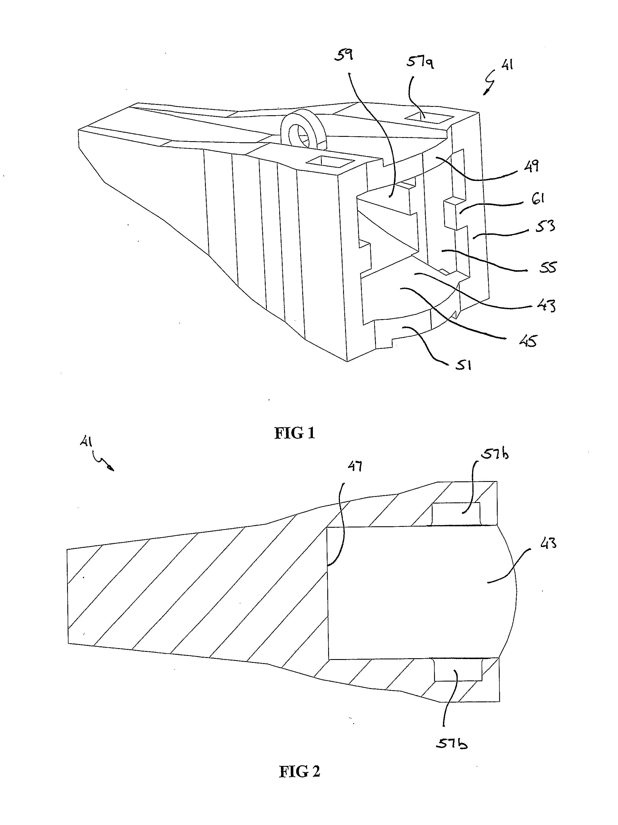
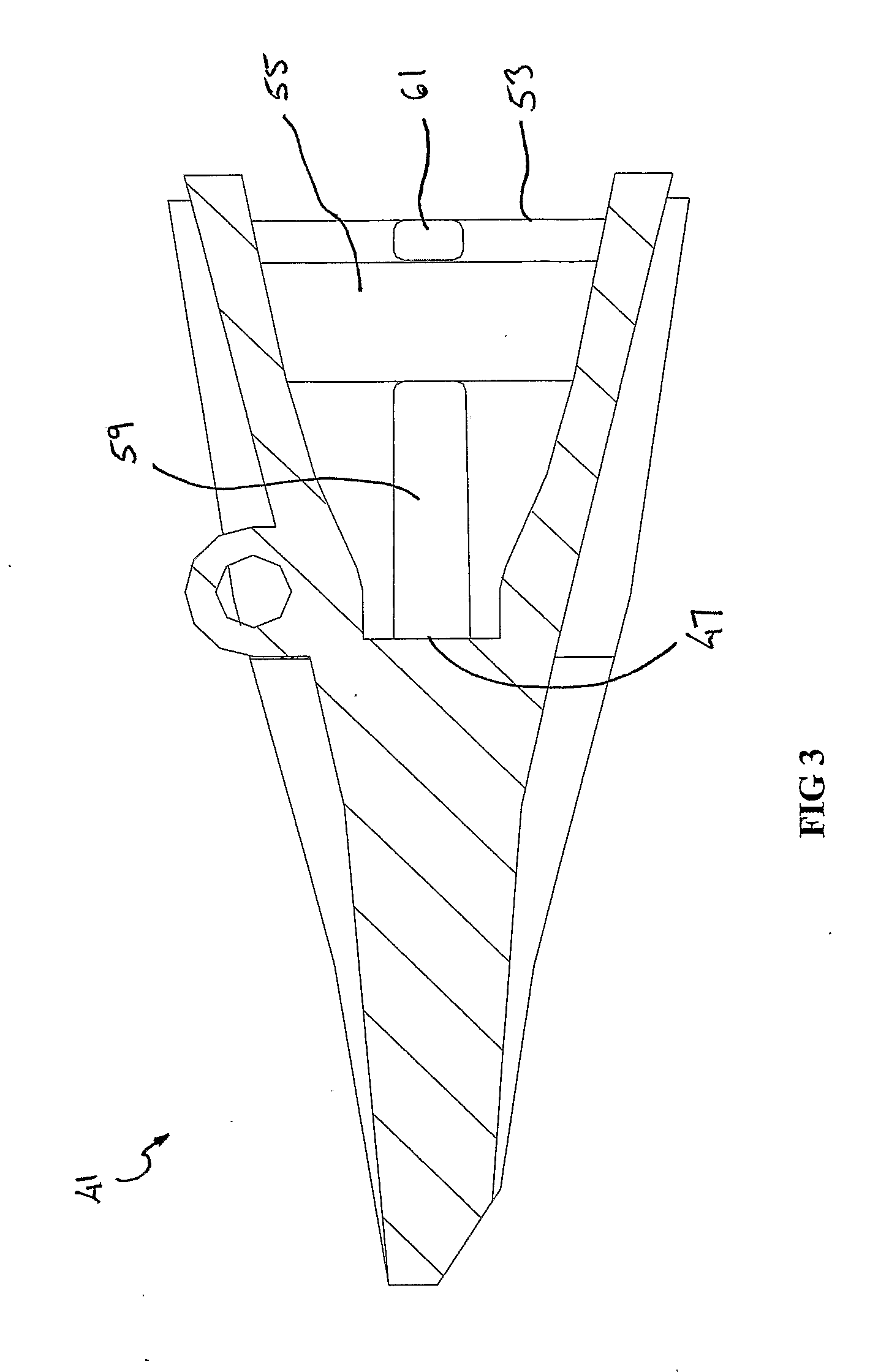
[0116]Referring to the FIGS. 1 to 19, the invention according to a first embodiment of the invention comprises a tooth and adaptor assembly 11 for use on earthmoving or similar machinery. The assembly 11 comprises an adaptor 21, having a first end 23 adapted to receive a tooth 41, with a locking mechanism 71 being received therein to lock the tooth 41 relative to the adaptor 21.

[0117]Shown in FIGS. 9 to 14 is the adaptor 21. The adaptor 21 has a second end 25 adapted to be secured to a bucket or like component on the earthmoving machinery (not shown). The configuration of the second end 25 varies according to its particular application.

[0118]The adaptor 21 comprises a nose 27 at the first end 23. The nose 27 diverges outwardly in a rearward direction from a front surface 29. The nose 27 comprises an upper surface 31, a lower surface 33, both having a curved contour, and two sidewalls 35.

[0119]Each sidewall 35 incorporates a first channel 37 extending longitudinally along the nose 27...


PUM


Abstract

Abstract A tooth and adaptor assembly (11) for use on earthmoving machinery, the assembly comprising an adaptor (21) adapted to be secured to a bucket or like component on the earthmoving machinery. The adaptor (21) comprising a nose (27) having an at least one sidewall (35) incorporating a first channel (37) and a second channel (39) angled relative to each other. The assembly (11) also a tooth (41) adapted to be received on the adaptor (41) and releasably secured thereto. The tooth comprises a socket (43) having sidewalls (53). At least one sidewall (53) incorporates a third channel (55) at an angle complementary to the second channel (39), such that when assembled the two channels (39, 55) co-operate to define an enclosure (91). An upper wall (49 of the socket (43) has at least one aperture (57) therethrough, and which is aligned with the third channel (55). The assembly (11) further comprises at least one locking mechanism (71) for locking the tooth (41) to the adaptor (21). The locking mechanism (71) having at least one projection (77) and adapted to be received through the aperture (57). During assembly the projection (77) moves inwardly with respect to the locking mechanism (71) as it enters the enclosure, the locking mechanism (71) moving towards its normal extended position when the projection (77) aligns with the first channel (37) wherein the assembly (11) is in its locked condition.

Description

FIELD OF THE INVENTION [0001]This invention relates particularly to the mining and construction industries and the use of earthmoving and similar machinery used in those industries. More particularly this invention relates to the wear components, namely the replaceable wear teeth on the excavator and the mode in which they are secured thereto.BACKGROUND ART [0002]Within the mining and construction industries machinery such as excavators and front end loaders are used to move debris for various purposes. This machinery is often used in an extremely abrasive environment resulting in extreme wear on components.[0003]The machinery often has a bucket having several teeth extending from its leading edge. These teeth experience substantial wear and may need to be replaced daily in some environments.[0004]To reduce downtime in replacing the teeth, various configurations have been developed which use an adaptor secured to the bucket of the machine, a tooth releasably retained on the adaptor ...

Claims


Application Information

Patent Timeline
Patent Type & Authority Applications(United States)
IPC IPC(8): E02F9/28
CPCE02F9/2825E02F9/2841E02F9/2833
Inventor ARMSTRONG, BRUCE
Owner BRADKEN OPERATIONS
Why Eureka
Try Eureka