Projection lens for a microlithographic projection exposure apparatus

a technology of exposure apparatus and projection lens, which is applied in the direction of photomechanical apparatus, printers, instruments, etc., can solve the problems of non-uniform illumination, aberration, and inability to accept imaging errors and/or contrast losses in the image plane of the optical system, and achieve the effect of improving the projection lens, low cost and reducing the disturbance of the polarization distribution

Inactive Publication Date: 2005-01-27
CARL ZEISS SMT GMBH
View PDF11 Cites 19 Cited by
  • Summary
  • Abstract
  • Description
  • Claims
  • Application Information

AI Technical Summary

Benefits of technology

[0012] It is therefore an object of the invention to improve a projection lens in such a way that the undesirable effects of disturbances in the polarization distribution can be reduced at low expense.

Problems solved by technology

If disturbances of said defined polarization distribution occur, it can result in unacceptable imaging errors and / or in contrast losses in the image plane of the optical system.
If it is not possible to suppress the stress-induced birefringence by suitable measures and to achieve compensation for the retardance caused by intrinsic birefringence, the disturbances in the polarization distribution caused by these effects have the result that aberrations occur in the desired intensity distribution downstream of a polarizing optical element.
If, for example, the object plane of a projection lens of a microlithographic projection exposure apparatus is uniformly illuminated and a disturbance of the polarization distribution occurs, undesirable local intensity fluctuations occur downstream of a polarization-selective beam-splitter layer that is transparent to light having undisturbed polarization.
The intensity fluctuations may result in a non-uniform illumination and, in particular, in fluctuations in the line widths of a photosensitive layer to be exposed in the image plane of the projection lens.
Such fluctuations in the line widths reduce the clock frequencies of the large-scale-integrated electrical circuits and are therefore undesirable.
Complete compensation for disturbances in the polarization distribution caused by intrinsic birefringence is, however, generally not possible by means of these measures.
However, it is precisely these additionally necessary measures that render the correction device disclosed in DE 198 07 120 A1 relatively expensive.

Method used


Image

  • Projection lens for a microlithographic projection exposure apparatus
  • Projection lens for a microlithographic projection exposure apparatus
  • Projection lens for a microlithographic projection exposure apparatus

Examples


Embodiment Construction

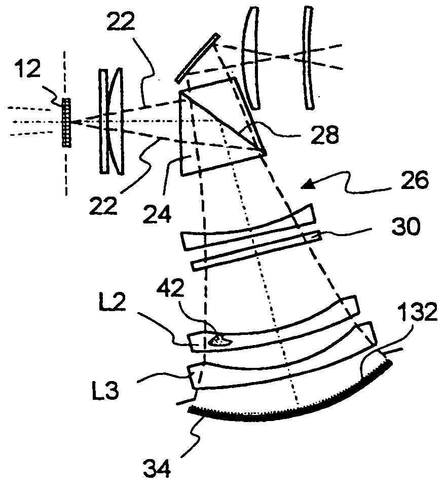
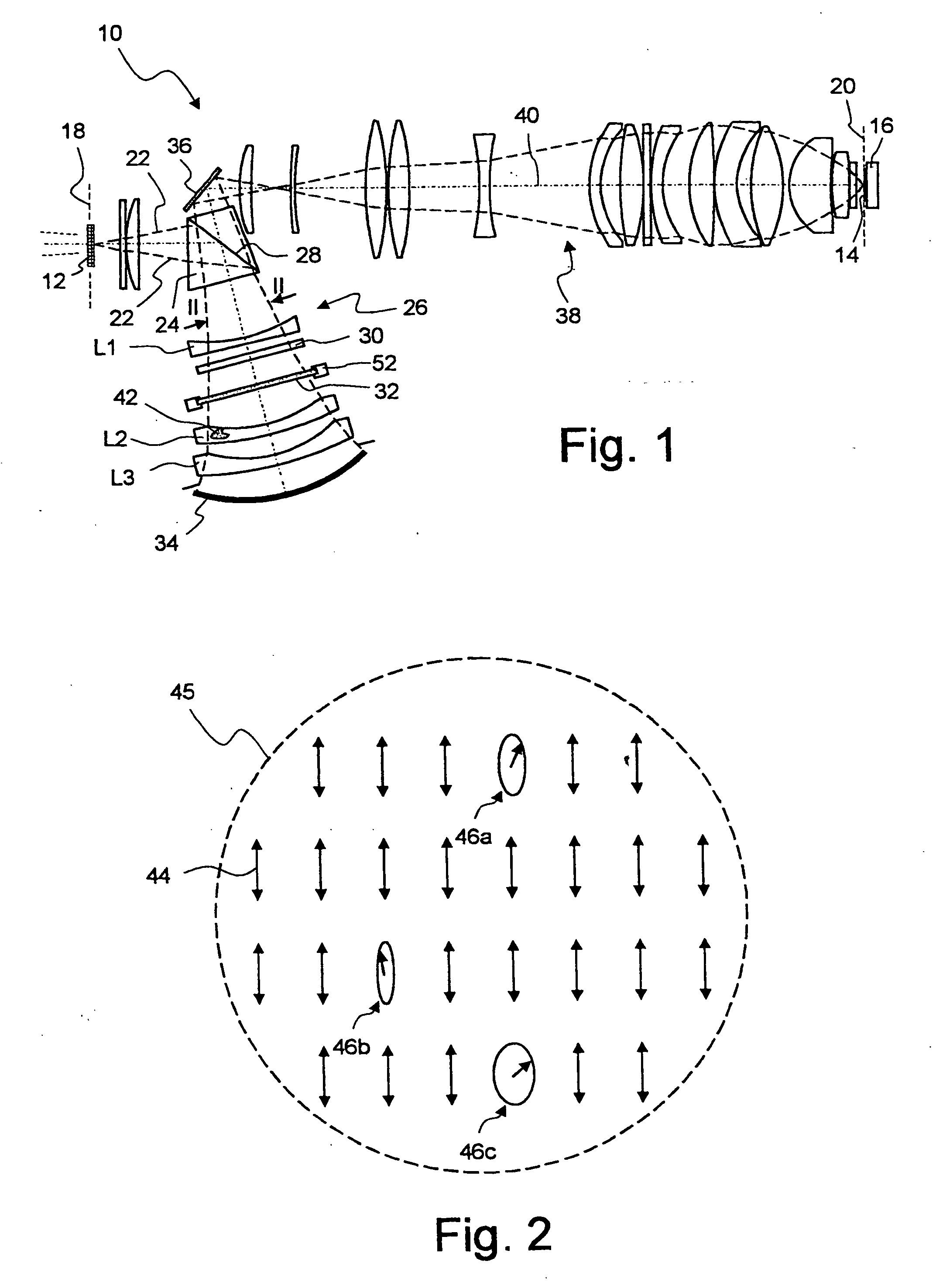
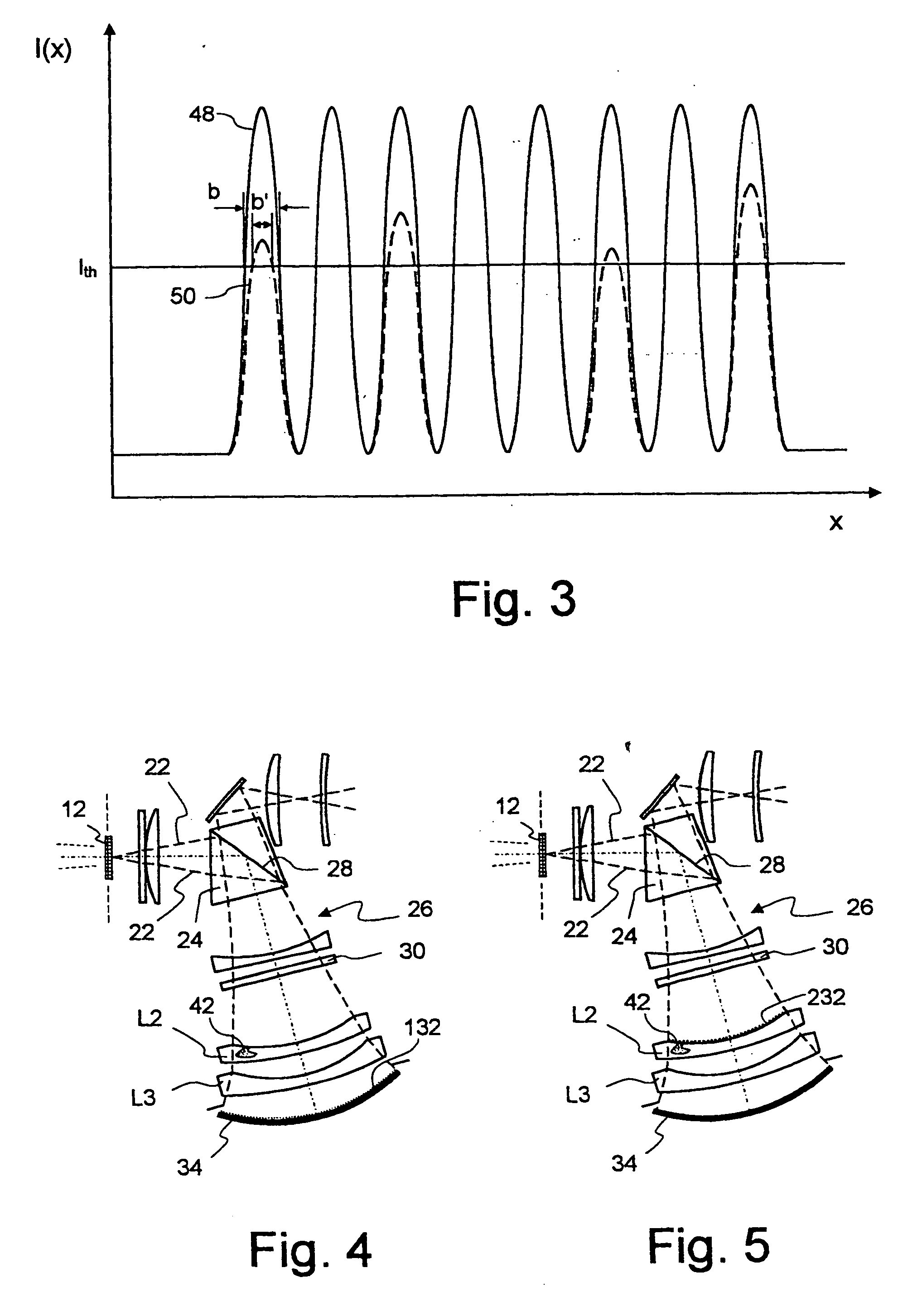
[0028]FIG. 1 shows, in simplified form, a projection lens of a microlithographic projection exposure apparatus in a meridional section. The projection lens, which is denoted in its entirety by 10, is provided to image, in a reduced form, structures contained in a reticle 12 on a photosensitive layer 14 that is deposited onto a substrate 16. The reticle 12 is disposed in an object plane 18 and the photosensitive layer 14 is disposed in an image plane 20 of the projection lens 10.

[0029] In FIG. 1, initially unpolarized projection light 22, as indicated by broken lines, is generated by an illumination system, not shown, of the projection exposure apparatus and has a wavelength λ=157 nm in the exemplary embodiment shown. The projection light 22 enters, after passing through the reticle 12 and two optical elements not denoted in greater detail, a catadioptric section 26 that is separated from the remaining part by a beam-splitter cube 24.

[0030] In the beam-splitter cube 24, a first pol...


PUM

PropertyMeasurementUnit
transmittanceaaaaaaaaaa
reflectanceaaaaaaaaaa
phase distributionaaaaaaaaaa

Abstract

A projection lens (10) for a microlithographic projection exposure apparatus has a first optical element, for example a birefringent lens (L2), that has polarization dependent properties causing intensity fluctuations in an image plane of the projection lens. These fluctuation may be produced by a second optical element (24), for example a polarization selective beam splitting layer (28), that is arranged downstream of the first optical element. A gray filter (32; 132; 232) disposed in the beam path reduces the intensity fluctuations.

Description

[0001] The following disclosure is based on German Patent Application No. 10329793.6, filed on Jul. 1, 2003, which is incorporated into this application by reference. BACKGROUND OF THE INVENTION [0002] 1. Field of the Invention [0003] The present invention plates to a projection lens for a microlithographic projection exposure apparatus. Such apparatuses are used for manufacturing microstructured devices such as integrated circuits. [0004] 2. Description of Related Art [0005] In numerous optical systems, a high imaging quality requires that the light passing through the optical system is in a defined polarization state over the entire beam cross section. Since said defined polarization state does not necessarily have to be constant over the beam cross section, this requirement is also referred to as “defined polarization distribution”. If disturbances of said defined polarization distribution occur, it can result in unacceptable imaging errors and / or in contrast losses in the image ...

Claims


Application Information

Patent Timeline
Patent Type & Authority Applications(United States)
IPC IPC(8): G02B13/14G02B17/08G02B27/28G03F7/20
CPCG02B13/14G02B17/08G02B17/0892G03F7/70566G03F7/70191G03F7/70225G02B27/286
Inventor GRUNER, TORALFMANN, HANS-JURGEN
Owner CARL ZEISS SMT GMBH
Why Eureka
Try Eureka