Liquid crystal display panel and liquid crystal display apparatus

a liquid crystal display and display panel technology, applied in non-linear optics, instruments, optics, etc., can solve the problems of user privacy not being protected, and the sacrifice of liquid crystal display privacy

Active Publication Date: 2018-04-24
BOE TECH GRP CO LTD +1
View PDF20 Cites 0 Cited by
  • Summary
  • Abstract
  • Description
  • Claims
  • Application Information

AI Technical Summary

Benefits of technology

[0018]In the liquid crystal display panel of the present invention, a view angle control layer is provided between the first polarizer and the second polarizer, the refractivity of the view angle control layer in the horizontal direction may be controlled by controlling the electric field in the horizontal direction applied to the view angle control layer, thus phase differences among light rays transmitted through the liquid crystal display panel may be controlled, and view angle of the liquid crystal display panel may be controlled. In the liquid crystal display apparatus of the present invention, the electric field in the horizontal direction applied to the view angle control layer may be adjusted in accordance with operational requirements to achieve objective of adjusting the view angle of the liquid crystal display apparatus.

Problems solved by technology

Although wide view angle becomes more and more important for functionality of a liquid crystal display, in some cases, wide view angle may sacrifice privacy of the liquid crystal display, that is, privacy of users cannot be protected.
Therefore, how to adjust or select the view angle of a liquid crystal display in accordance with operational requirements becomes a technical problem to be solved in the art.

Method used


Image

  • Liquid crystal display panel and liquid crystal display apparatus
  • Liquid crystal display panel and liquid crystal display apparatus
  • Liquid crystal display panel and liquid crystal display apparatus

Examples


Embodiment Construction

[0037]Specific embodiments of the present invention will be described below in detail with reference to the drawings. It should be understood that, the specific embodiments described here are only used for clarifying or explaining the invention, but the invention is not limited thereto.

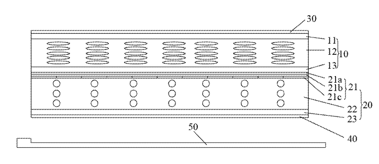
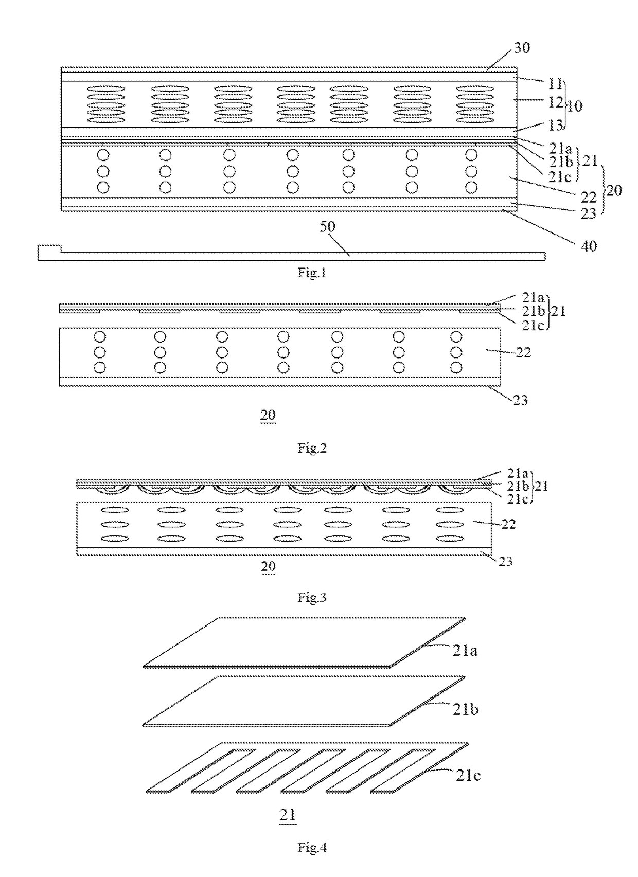
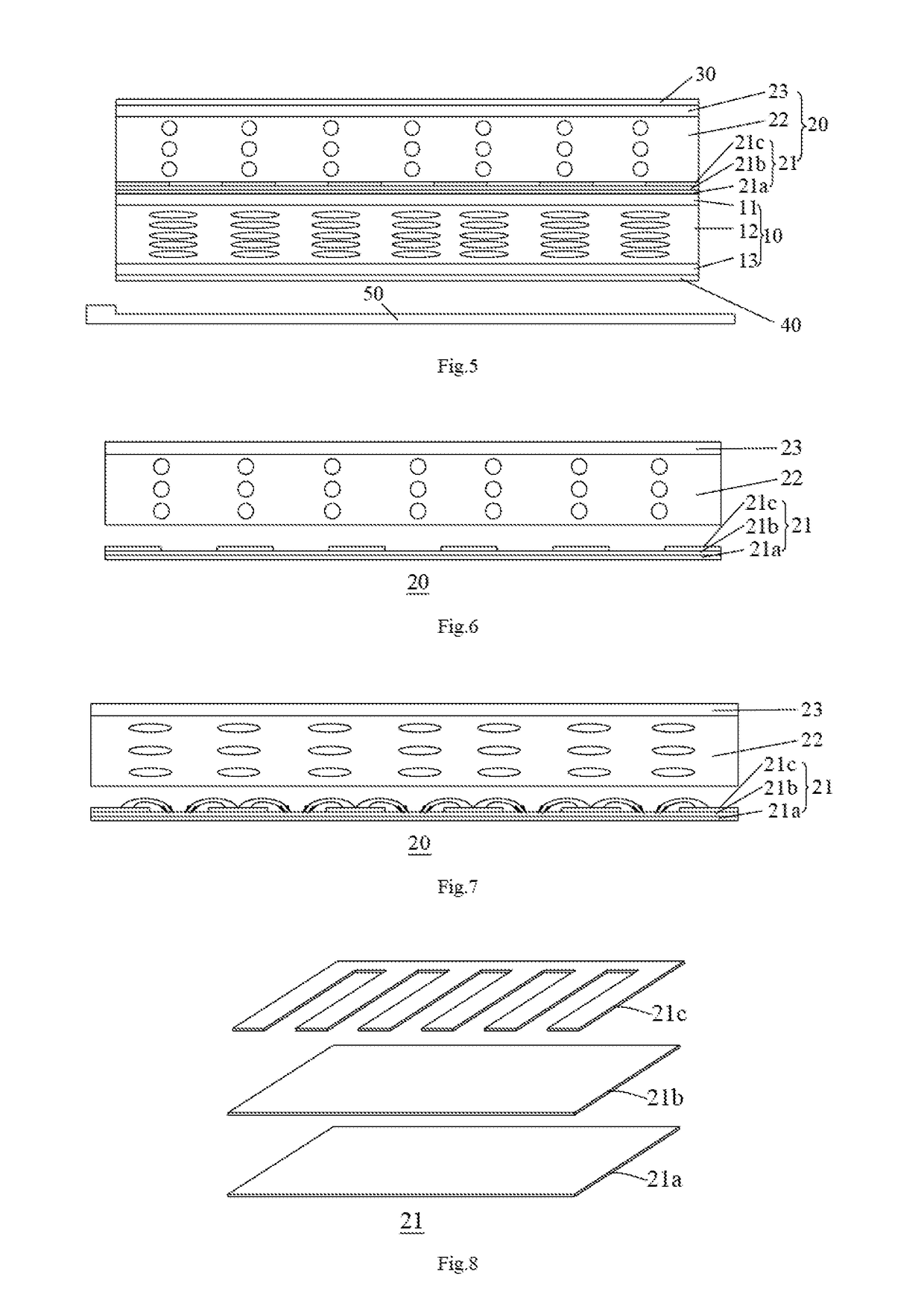
[0038]As shown in FIGS. 1, 5, 9 and 13, an aspect of the present invention provides a liquid crystal display panel comprising a first polarizer 30, a second polarizer 40 and a liquid crystal cell 10 provided between the first polarizer 30 and the second polarizer 40, wherein the liquid crystal display panel further comprises a view angle control layer 20 provided between the first polarizer 30 and the second polarizer 40, a refractivity of the view angle control layer 20 in a horizontal direction can vary with the electric field in the horizontal direction applied to the view angle control layer 20.

[0039]It should be understood that, the view angle control layer 20 may be provided above or below the l...


PUM

PropertyMeasurementUnit
electric fieldaaaaaaaaaa
electric birefringenceaaaaaaaaaa
view angleaaaaaaaaaa

Abstract

The present invention provides a liquid crystal display panel and a liquid crystal display apparatus. The liquid crystal display panel comprises a first polarizer, a second polarizer and a liquid crystal cell provided between the first polarizer and the second polarizer, wherein the liquid crystal display panel further comprises a view angle control layer provided between the first polarizer and the second polarizer, the refractivity of the view angle control layer in a horizontal direction can vary with an electric field in the horizontal direction applied to the view angle control layer.

Description

[0001]This is a National Phase Application filed under 35 U.S.C. 371 as a national stage of PCT / CN2013 / 086157, filed Oct. 29, 2013, and claims priority benefit from Chinese Application No. 201310294415.X, filed Jul. 12, 2013, the content of each of which is hereby incorporated by reference in its entirety.TECHNICAL FIELD[0002]The present invention relates to the field of liquid crystal display technology, and particularly, to a liquid crystal display panel and a liquid crystal display apparatus.BACKGROUND ART[0003]Liquid crystal displays have been widely used in consumer electronics such as television, mobile phone, and computer display, and gradually replace cathode ray tube (CRT) displays to become a mainstream of displays, because the liquid crystal displays have advantages such as small volume, light weight, low drive voltage and low power consumption, and excellent image quality in recent years, market of liquid crystal displays is increased, and particularly, in application fo...

Claims


Application Information

Patent Timeline
Patent Type & Authority Patents(United States)
IPC IPC(8): G02F1/1343G02F1/1347G02F1/1335G02F1/137G02F1/13G02F1/1333
CPCG02F1/1323G02F1/137G02F1/1347G02F1/133345G02F1/133528G02F1/13439G02F2001/13793G02F1/134363G02F1/13793
Inventor FENG, YUANMING
Owner BOE TECH GRP CO LTD
Why Eureka
Try Eureka