Flowswitch with O-ring seal

a flow switch and seal technology, applied in the field of flow switches, can solve the problems of shafts without o-ring grooves and unbalanced devices, and achieve the effect of less mechanical wear

Active Publication Date: 2008-10-23
XYLEM IP HLDG
View PDF3 Cites 4 Cited by
  • Summary
  • Abstract
  • Description
  • Claims
  • Application Information

AI Technical Summary

Benefits of technology

[0040]Minimal movement of moving part

Problems solved by technology

However, disadvantages of this design include the following:
However, the valve device design has an unbalanced device since the shaft only has an O-ring on one end, and the cam-like relationship between the flat portion and the bottom is likely to contribute to increased friction, especially as the

Method used


Image

  • Flowswitch with O-ring seal
  • Flowswitch with O-ring seal
  • Flowswitch with O-ring seal

Examples


Embodiment Construction

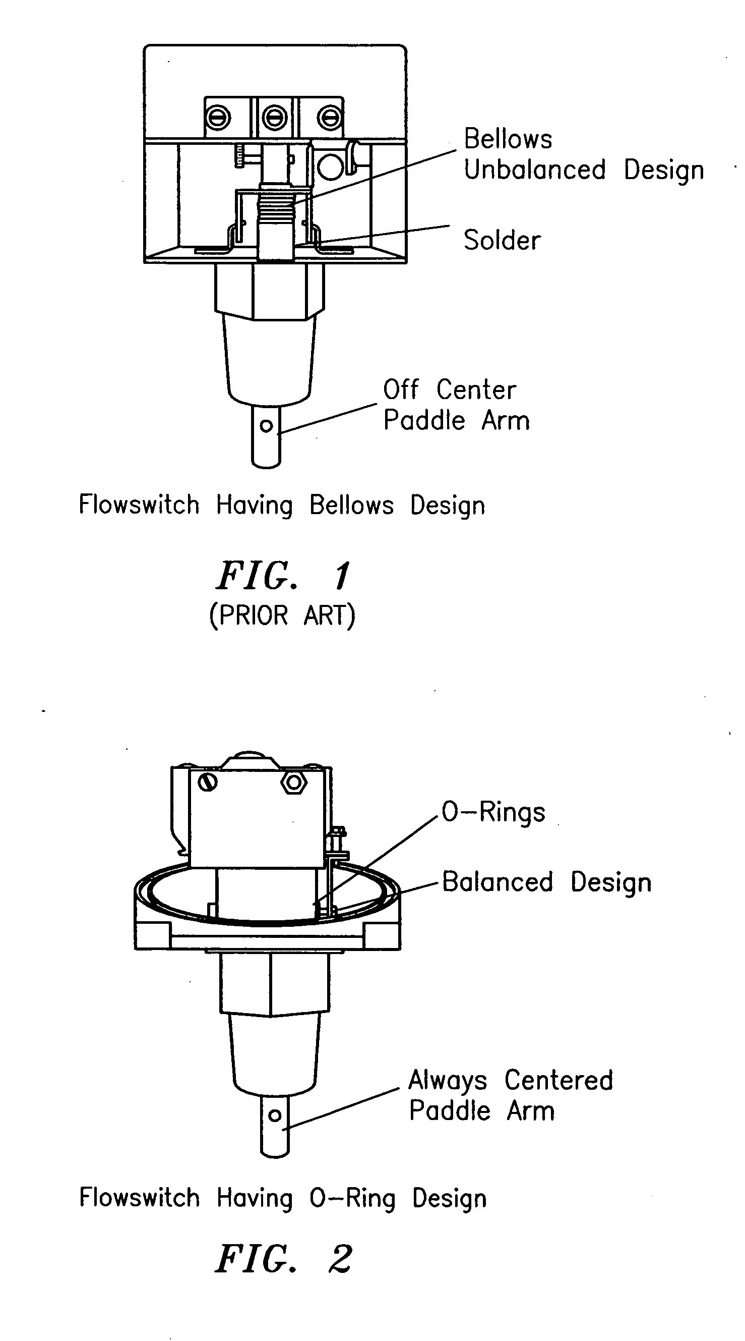
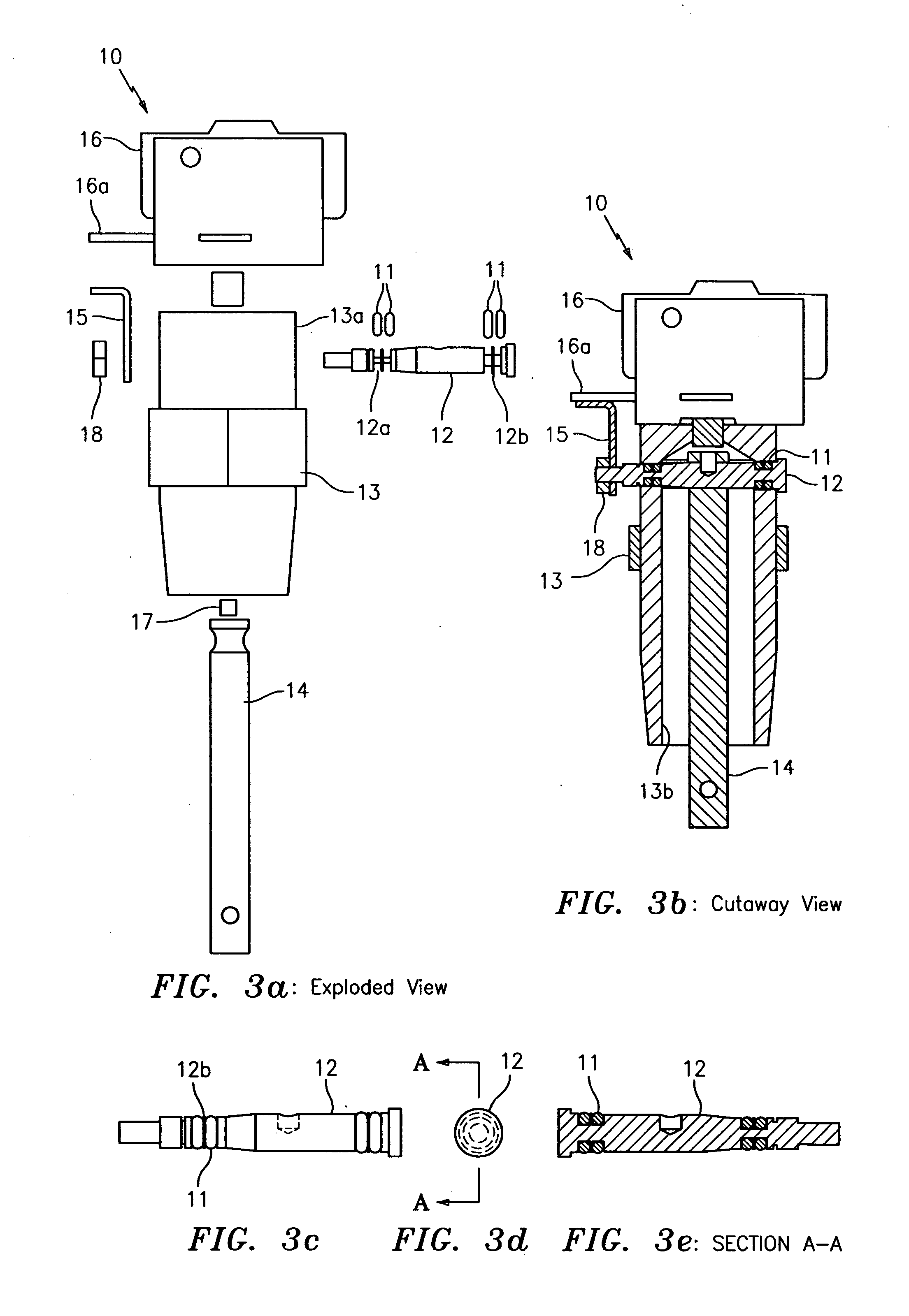
[0068]FIGS. 2-3k show an O-ring flowswitch generally indicated as 10 according to the present invention, featuring by way of example four lubricated O-rings 11 installed onto a pivot rod 12 with machined or formed o-ring grooves 12a and machined or formed flanges 12b that separate the O-rings 11. As shown, two o-rings are installed on each side of the pivot rod 12.

[0069]The pivot rod 12 is passed through an aperture 13a in a flowswitch base 13 and a paddle arm 14 that is arranged in the middle of an aperture 13b in the flowswitch base 13. The pivot rod 12 and aperture 13a are suitably dimensioned so that the o-rings 11 provide a seal between the fluid being sensed and the outside environment. The pivot rod 12 and aperture 13a are also suitably dimensioned so that the o-rings 11 also act as a bearing on which the pivot rod 12 rotates when the paddle arm 14 moves as fluid is flowing past the flowswitch 10. The scope of the invention is not intended to be limited to any such dimensioni...


PUM


Abstract

The present invention provides a flowswitch for installing in piping, featuring a flowswitch base having an inner cavity; a pivot rod being arranged for rotating in the flowswitch base, the pivot rod having a pair of O-ring grooves; a paddle arm being coupled to the pivot rod inside the cavity, for moving in response to fluid flowing in the piping and rotating the pivot arm; lubricating O-rings being installed onto the pivot rod with each O-ring arranged in a respective O-ring groove for providing a respective seal between fluid being sensed and the outside environment and acting as a bearing on which the pivot rod rotates when the paddle arm moves, the grooves acting to holding the O-rings in place on the pivot arm in response to pressurized fluid flowing in the piping; and an actuating arm being coupled between the pivot arm and the pivot rod for actuating a switch when the pivot arm rotates.

Description

BACKGROUND OF THE INVENTION[0001]1. Field of the Invention[0002]The present invention relates to a flowswitch; and more particularly to a flowswitch used to monitor and detect the flow or no flow condition of liquids in pipelines.[0003]2. Brief Description of Related Art[0004]Flowswitches are used to monitor and detect the flow or no-flow condition of liquids in pipelines. A flowswitch can make or break an electrical signal when flow or no-flow is detected and is used to actuate a signal when flow stops, start a motor with flow, shut off an alarm when flow is adequate, or stop a motor with no flow. A flowswitch typically has a wetted side that installs into the piping that carries the liquid that will actuate the switch, and a dry side with the electrical connections.[0005]One known flowswitch is shown in FIG. 1 and has a bellows design that has been in the field for over 20 years and customers are familiar with the design. However, disadvantages of this design include the following...

Claims


Application Information

Patent Timeline
IPC IPC(8): F16K31/02
CPCH01H35/40
Inventor GARVEY, JOHN C.
Owner XYLEM IP HLDG
Why Eureka
Try Eureka