
Train driving locus detection method based on phase-sensitive optical time-domain reflectometer

A time-domain reflectometer and phase-sensitive light technology, applied in the field of train trajectory detection, optical time-domain optical fiber sensing technology and train trajectory detection, can solve the problem of poor anti-electromagnetic interference ability, circuit system failure, hidden danger of driving safety, etc. problems, to achieve the effect of long service life, low maintenance cost, and elimination of some noise

Active Publication Date: 2017-04-26
南京富岛信息工程有限公司
View PDF4 Cites 6 Cited by
  • Summary
  • Abstract
  • Description
  • Claims
  • Application Information

AI Technical Summary

Problems solved by technology

The automatic train control system (ATC) or the high-speed train control system (CTCS) in the railway rail transit system, when the track circuit encounters geological disasters such as severe weather conditions, lightning high-voltage shocks, or debris flows, it is easy to cause circuit system failures. Hazards to driving safety
At present, the on-board control equipment of trains can only rely on the signals provided by ground facilities such as track circuits, ground transponders or ground wireless communication base stations to obtain the information of the current line, which has the disadvantages of heavy construction, high maintenance costs, and poor anti-electromagnetic interference ability

Method used

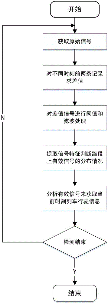

Image

  • Train driving locus detection method based on phase-sensitive optical time-domain reflectometer
  • Train driving locus detection method based on phase-sensitive optical time-domain reflectometer
  • Train driving locus detection method based on phase-sensitive optical time-domain reflectometer

Examples


Embodiment Construction

[0023] The present invention will be further described below in conjunction with the accompanying drawings and examples of implementation.

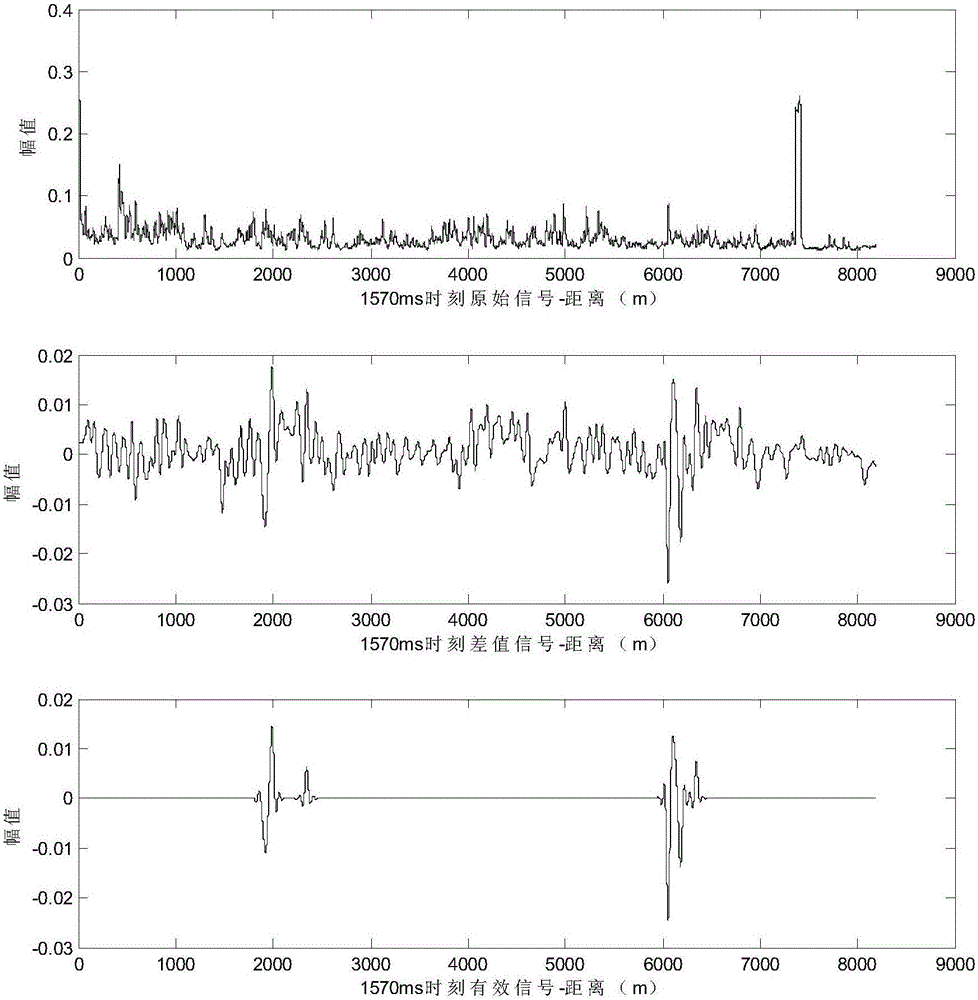
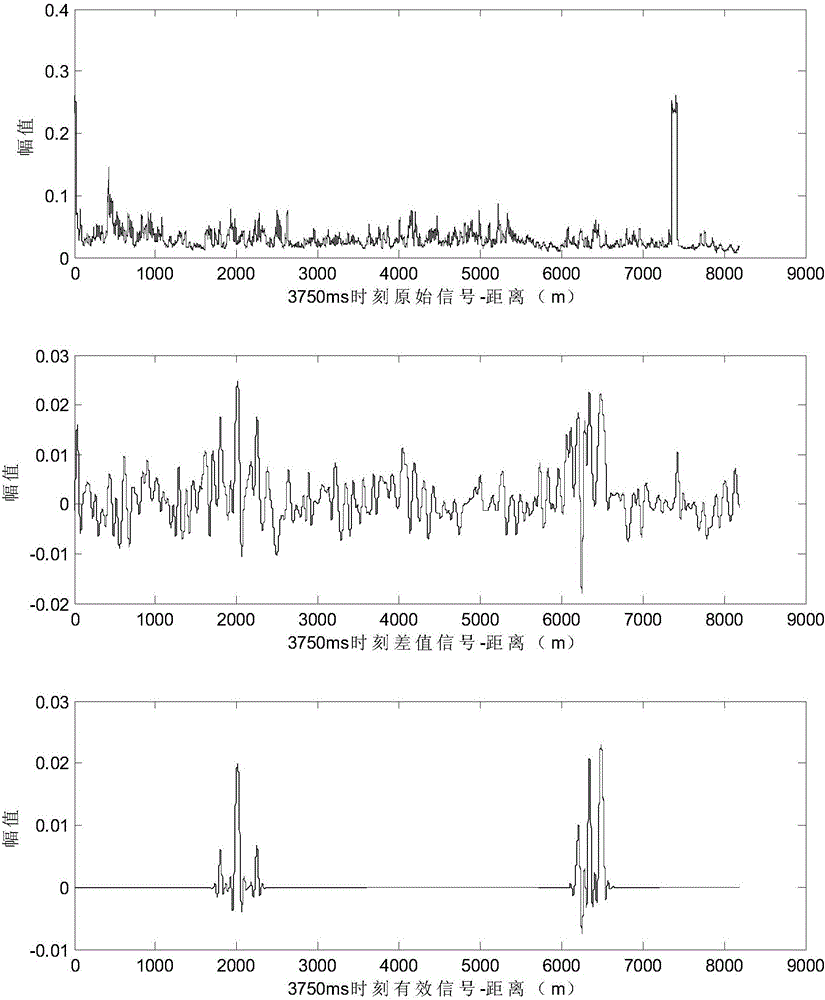
[0024] According to attached figure 1 As shown in the flow chart of the implementation of the method, the present invention first uses the Φ-OTDR system to collect the original signal of a certain section of the high-speed train line in a certain period of time at a southern high-speed railway station, that is, the backscattered light signal along the rail track, as shown in the attached figure 2 Shown in the original signal in . This signal reflects the vibration signal along the track, with image 3 And attached Figure 4 The original signals in are similar, only differing in time.

[0025] The present invention first performs wavelet denoising on the collected original signal, adopts sym8 wavelet decomposition, and adopts existing wavelet library functions in MATLAB software to realize.

[0026] In order to solve the problem of re...


PUM


Abstract

The invention provides a train driving locus detection method based on a phase-sensitive optical time-domain reflectometer. According to the method, the vibration information of a trainin a driving process is acquired through employing phi-OTDR, difference calculation for signals at two adjacent different moments is carried out, a threshold and low pass filtering processing based on wavelet transformation are employed to carry out amplitude characteristics extraction of the difference signals after processing, the useful signals are distinguished from external interference signals according to the amplitude characteristics, and the present position, the speed and the driving direction of the train can be determined lastly according to the identified useful signals. Through the method, optical cables near rails in the prior art are only utilized, no extra construction workload is required, the method further has properties of simple mounting, long service life, low maintenance cost and strong anti-interference capability, large-scale distributed detection can be realized, a reliable auxiliary determination means can be provided for present driving of the train, and the method has important potential application values for safety driving of the train.

Description

technical field [0001] The invention is a train track detection method based on phase-sensitive optical time domain reflectometer (Φ-OTDR) technology, specifically relates to the field of optical time domain optical fiber sensing technology and train track detection, especially a method for detecting train track online real-time detection method. Background technique [0002] Accurately grasping the current position of the train in real time is crucial to the safety of railway operation. The automatic train control system (ATC) or the high-speed train control system (CTCS) in the railway rail transit system, when the track circuit encounters geological disasters such as severe weather conditions, lightning high-voltage shocks, or debris flows, it is easy to cause circuit system failures. Bring hidden danger to driving safety. At present, the train on-board control equipment can only rely on signals provided by ground facilities such as track circuits, ground transponders, ...

Claims


Application Information

Patent Timeline
Patent Type & Authority Applications(China)
IPC IPC(8): G01S11/12G01S17/58
CPCG01S11/12G01S17/58
Inventor 费树岷丁宁陈夕松曹忠国张良朝
Owner 南京富岛信息工程有限公司
Learn More