
Optical joystick module

a joystick module and optical technology, applied in the field of switch mechanisms, can solve the problems of extreme warehousing and product handling environment, inconvenient installation, and reduced control of other functions,

Inactive Publication Date: 2006-04-11
ILLINOIS TOOL WORKS INC
View PDF5 Cites 0 Cited by
  • Summary
  • Abstract
  • Description
  • Claims
  • Application Information

AI Technical Summary

Benefits of technology

[0015]An advantage of the present invention is providing a joystick module that withstands extreme conditions of heat, cold and contamination.
[0016]Another advantage of the present invention is providing a joystick module having few parts subjected to mechanical wear.
[0017]A further advantage of the present invention is providing an optical joystick module having automatic centering of the joystick toggle arm for returning the control to a home position.
[0018]Still another advantage of the present invention is providing a compact joystick control module.
[0019]Other features and advantages of the invention will become apparent to those skilled in the art upon review of the following detailed description, claims and drawings in which like numerals are used to designate like features.

Problems solved by technology

However, known mechanical joystick modules are inconveniently large, thereby reducing the number of controls for other functions that can be included conveniently in a single grip, for example.
Further, warehousing and product handling environments can be extreme.
For example, lift trucks are used in refrigerated facilities, and may move continuously and repetitively between warm and cold air areas.
Lift trucks often are used outdoors and subjected to weather extremes.
Further, lift trucks also are used in dirty, dusty environments.
Mechanical joysticks switches can fail if subjected to such extreme conditions for a prolonged period of time.
As a result of the mechanical mechanism therein, known joystick modules which have anticipated lifetimes that are inconveniently short, requiring periodic replacement throughout the life of a fork lift truck.

Method used


Image

  • Optical joystick module
  • Optical joystick module
  • Optical joystick module

Examples


Embodiment Construction

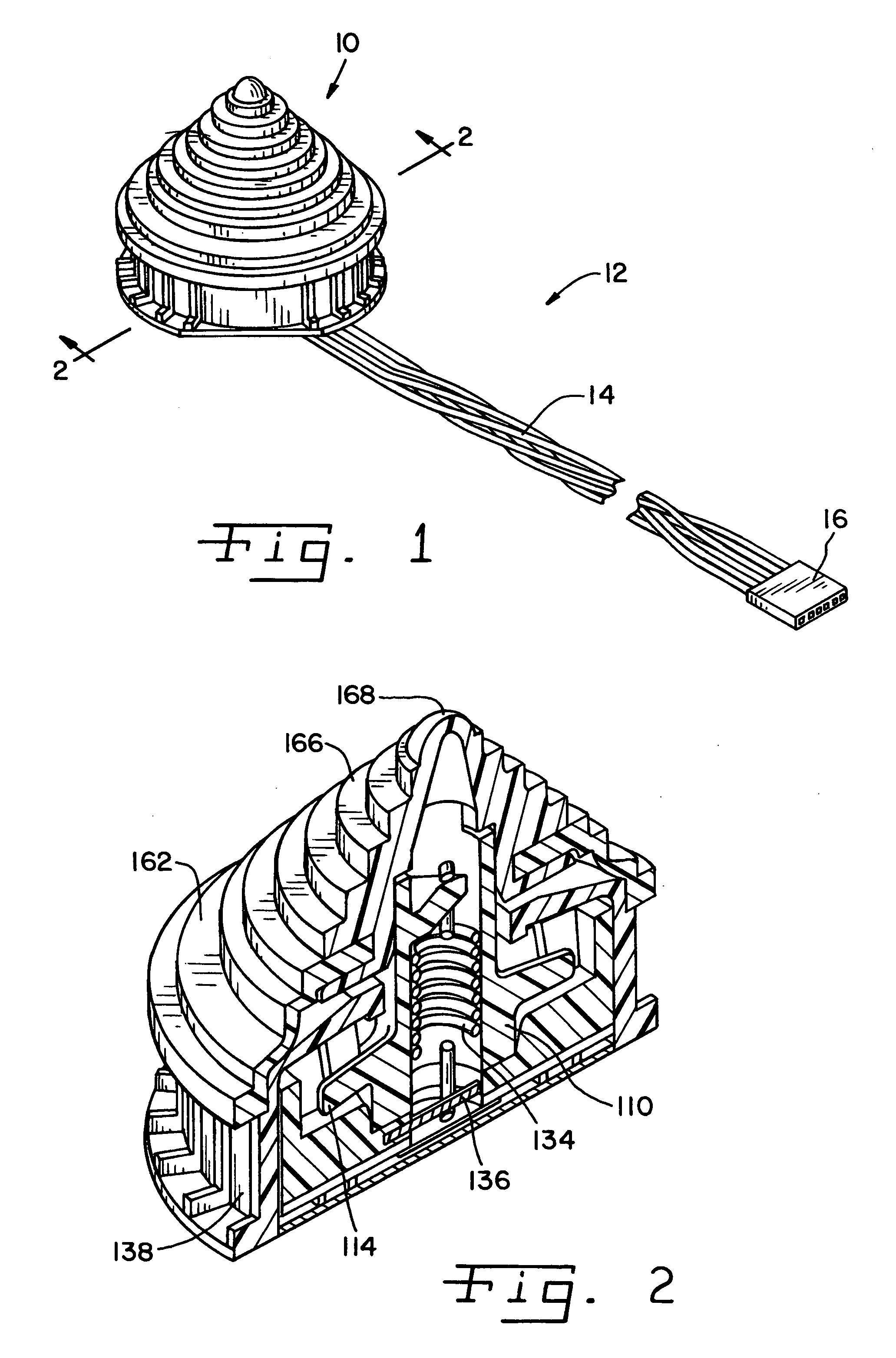
[0029]Referring now more specifically to the drawings and to FIG. 1 in particular, a joystick module 10 in accordance with the present invention is shown. Joystick module 10 is part of a control 12 that further includes a plurality of signal lines 14 and a connector 16. Control 12 can be connected to a controller, signal processor or the like (not shown) for providing user input and control for operation of a device, such as, for example, tilt control of forks on a lift truck. However, those skilled in the art will understand readily that joystick module 10 and control 12 can be used in other applications and for other purposes as well.

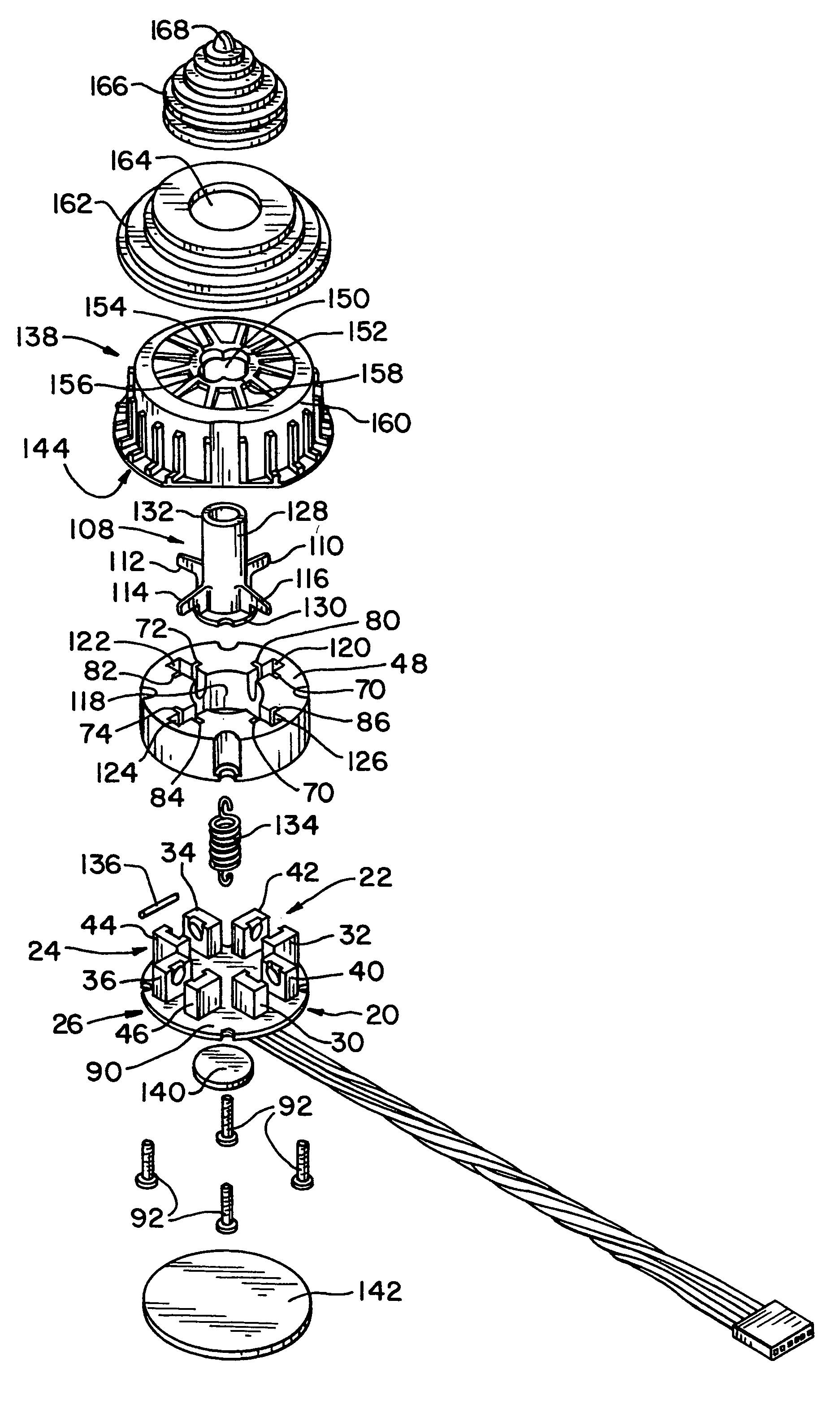
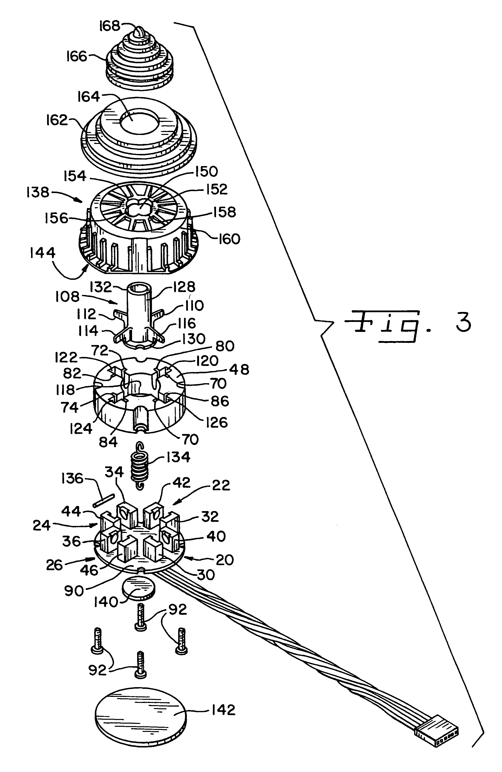
[0030]With reference now to FIG. 3, an exploded view of joystick module 10 is shown. Module 10 includes a plurality of opto-electronic switches 20, 22, 24 and 26, and as shown includes four opto-electronic switches 20, 22, 24 and 26. Each switch 20, 22, 24 and 26 includes a light source in the way of a light emitter 30, 32, 34 and 36, respectively, an...


PUM


Abstract

A joystick module in which a toggle arm controls movement of a plurality of shutters, with each shutter arranged between a light receiver and a light emitter. Control of the light from the light receiver to the light emitter of each pair provides signal information for controlled operation of an activity.

Description

CROSS REFERENCE TO RELATED APPLICATION[0001]This application claims benefit to U.S. Provisional Application Ser. No. 60 / 333,782 filed on Nov. 28, 2001.FIELD OF THE INVENTION[0002]The present invention relates generally to switch mechanisms, and, more particularly to joystick modules for controlling apparatus movement in multiple directions.BACKGROUND OF THE INVENTION[0003]Material handling equipment, such as lift trucks and the like, employ elevating mechanism for lifting and moving loads. In a common configuration for lift trucks, a pair of forks are slid under a load, and then raised to lift the load.[0004]The load can then be moved and placed in another location, or stacked on other articles.[0005]Since loads are not always piled evenly, surfaces are irregular, and articles themselves can be of different shapes, it is often necessary to tilt the forks forward or backward and from side to side to evenly engage the load, or to disengage from the load. Lift trucks are designed with ...

Claims


Application Information

Patent Timeline
Patent Type & Authority Patents(United States)
IPC IPC(8): H03K17/94G05G9/047
CPCG05G9/047G05G2009/04759
Inventor ORRICO, MARIO M.DANEK, DANIEL J.
Owner ILLINOIS TOOL WORKS INC
Learn More