Drill bit and method for grinding a drill bit

a drill bit and drill bit technology, applied in the direction of twist drills, manufacturing tools, wood boring tools, etc., can solve the problems of increasing the loading of the drill bit, and achieve the effect of keeping the mechanical load that occurs during drilling low

Inactive Publication Date: 2006-01-24
KENNAMETAL INC
View PDF21 Cites 49 Cited by
  • Summary
  • Abstract
  • Description
  • Claims
  • Application Information

AI Technical Summary

Benefits of technology

[0011]A drill tip of this type has the significant advantage that, on account of the curved, ridge-free surface with the radius of curvature R, therefore because the surface has a profile without shoulders, the load on the drill tip during drilling is low. In particular, no stress peaks occur in the area of the chisel edge surfaces of the type that occur on conventionally ground drill tips.
[0014]In one particularly advantageous embodiment, the drill bit is realized in the form of a replaceable insert for a drill base element. This type of two-part drill, consisting of a drill bit and drill base element, has the major advantage that the drill bit, which is subject to wear, can be easily replaced. The drill base element is generally exposed to much less wear, so that its useful life is several times longer than the useful life of the drill bit. By realizing the drill bit in the form of a replaceable insert, operating costs can therefore be reduced significantly. Moreover, the drill base element can be realized from a more economical and thus generally softer material than the material of which the drill bit is made.
[0016]The grinding wheel and drill bit are thereby guided toward each other in a complex three-dimensional grinding process, so that the drill bit is ground in the desired manner without the requirement for two separate grinding processes. On account of the continuous grinding process, no ridges are formed in the area of the clearance face and chisel edge surface of the type that would be unavoidably formed in a two stage grinding process. Therefore, as a result of the three-dimensional guidance of the drill tip and the grinding wheel, the two conventional grinding steps are therefore combined into one grinding step. The advantages of this method are reflected in, among other things, the curvature of the clearance face. On account of the shoulder-less and ridge-less profile of the ground surfaces of the drill tip, the load on the drill tip during drilling is also kept low.
[0017]One other possible advantage of the above-described drill tip design is that the power needed to rotate the drill during a cutting or drilling operation in some materials can be reduced by as much as approximately 30% over drill tips of the prior art, such as shown in FIG. 1 of this application. Therefore the energy requirement for operation of a drive or motor mechanism to rotate the drill during drilling is reduced.
[0024]The rake angle is preferably set between a positive rake angle of +5° and a negative rake angle of −5°. The advantage of the method described above is particularly apparent in the realization of a positive rake angle, which can be achieved easily and without problems using the method described above.

Problems solved by technology

In the area of the chisel edge, this ridge causes stress peaks that lead to increased loading on the drill bit.

Method used


Image

  • Drill bit and method for grinding a drill bit
  • Drill bit and method for grinding a drill bit
  • Drill bit and method for grinding a drill bit

Examples


Embodiment Construction

[0043]Equivalent parts in the figures are identified by the same reference numbers.

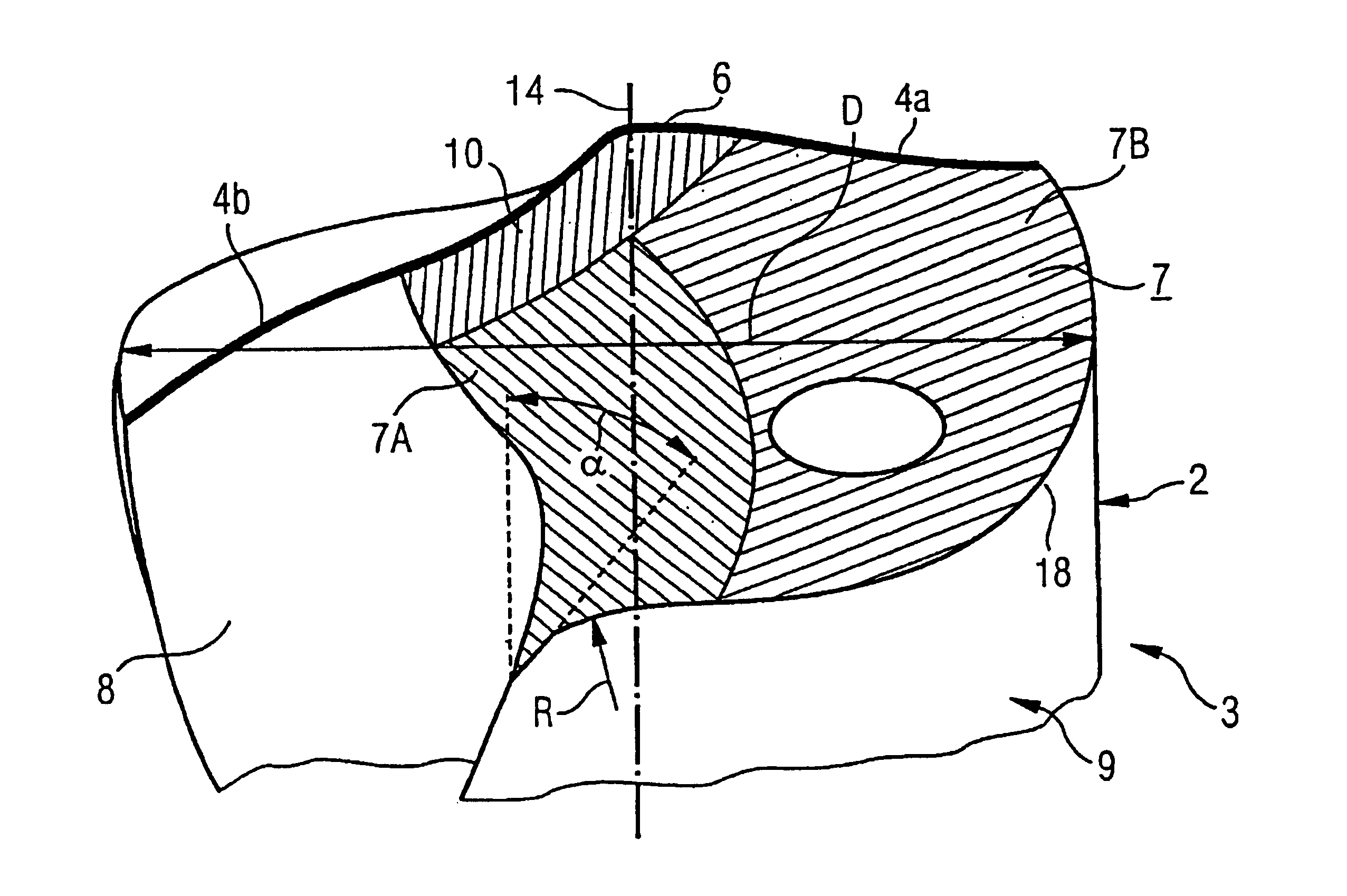
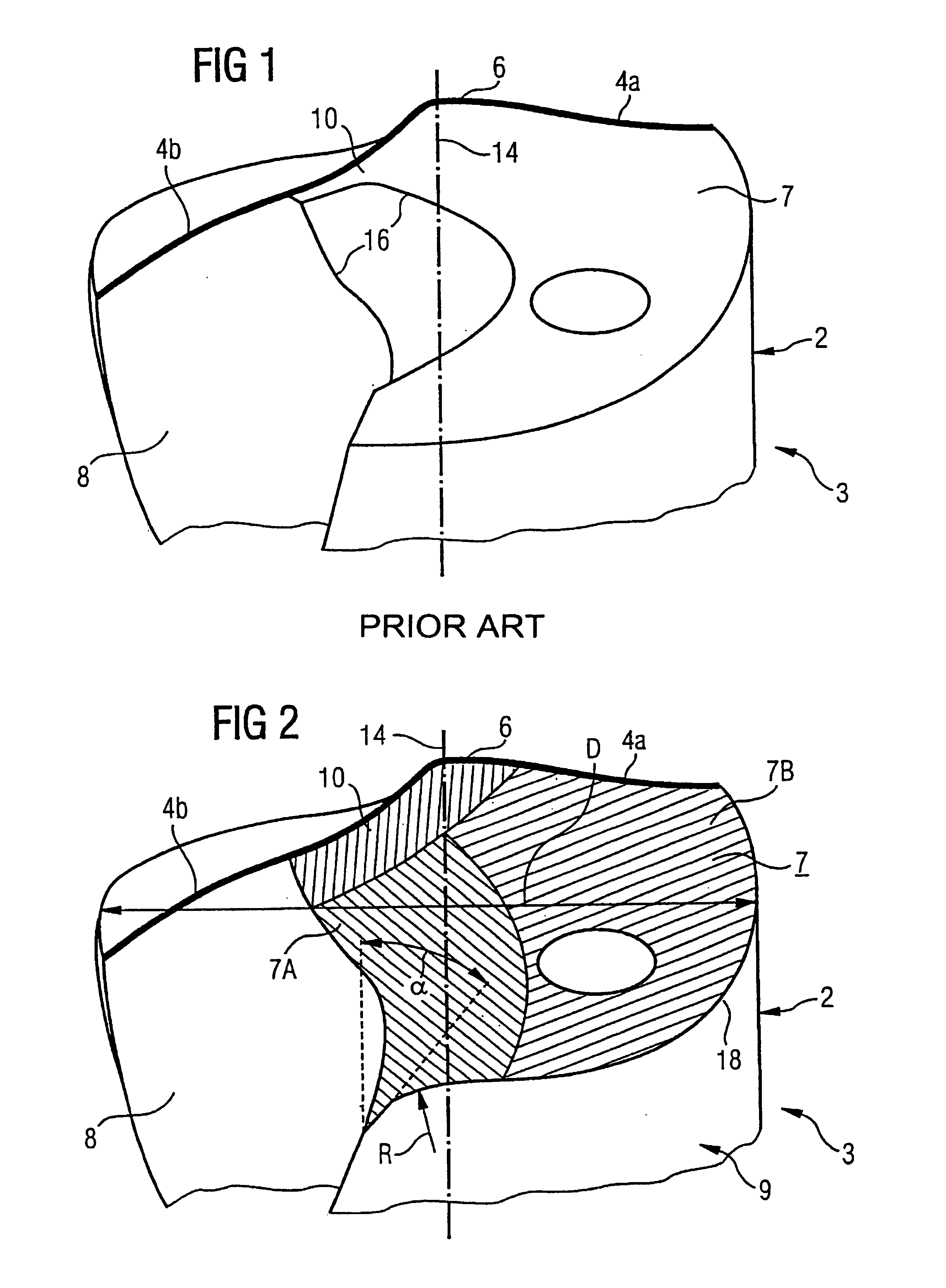
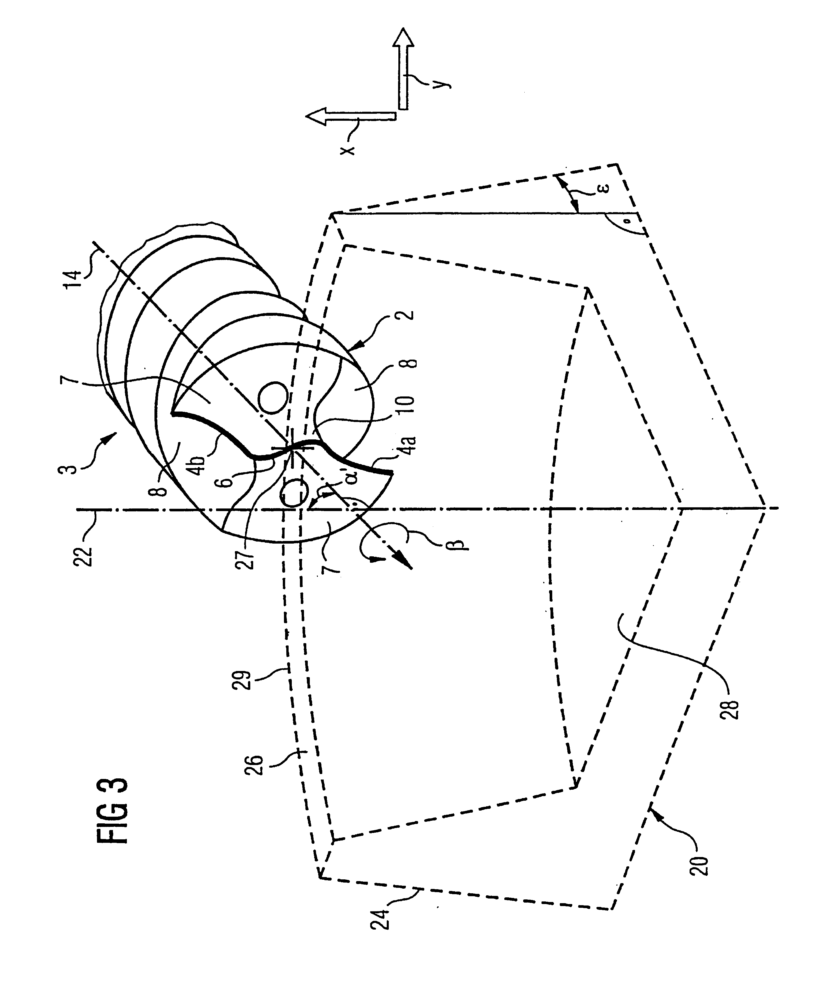
[0044]A drill bit 2 of a twist drill 3 that has been ground according to a method of the prior art (FIG. 1) and one that has been ground according to a method taught by an embodiment of the invention (FIG. 2) are contrasted in FIGS. 1 and 2. The drill bit 2 has two major cutting edges 4a, 4b, which are joined together via a roughly S-shaped chisel edge 6. The major cutting edges 4a, 4b and the chisel edge 6 are depicted in wider lines for purposes of illustration. The cutting edges formed by the major cutting edges 4a, 4b and chisel edge 6 extend over the entire drill bit 2. The drill bit 2 is designed to have mirror symmetry. The drill bit 2 is explained below with reference to one of the two mirror-image sides, starting from the major cutting edge 4a. Adjacent to it is a clearance face 7 that extends to a flute 8. The flute 8 begins in the drill bit 2 and runs in a spiral pattern in the flute area 9...


PUM

PropertyMeasurementUnit
pivot angleaaaaaaaaaa
rake angleaaaaaaaaaa

Abstract

The invention relates to a drill bit (2), having main cutting edges (4a, 4b) which are connected together by a transversal cutting edge (6). An open surface (7) which extends into a flute (8) lies adjacent to each main cutting edge. The drill bit (2) is ground, in particular, during a continuous three-dimensional grinding process in such a way that the open surface (7) forms a continuous curved surface which follows a radius of curvature (R) running from the main cutting edge (4a) in the direction of the flute (8). The continuous grinding process, in comparison to a conventional two-stage process, produces an improved drill bit geometry which is devoid of ridges (16). The ridge-free configuration reduces the mechanical stress during drilling to a minimum.

Description

[0001]This application is a Continuation-In-Part application of International Patent Application No. PCT / EP00 / 11174, filed on Nov. 11, 2000, which claims priority from Federal Republic of Germany Patent Application No. 199 55 172.3, filed on Nov. 16, 1999. International Patent Application No. PCT / EP00 / 11174 was pending as of the filing date of this application. The United States was an elected state in International Patent Application No. PCT / EP00 / 11174.BACKGROUND OF THE INVENTION[0002]1. Field of the Invention[0003]The invention relates to a drill bit and a method for grinding a drill bit having two major cutting edges connected via a chisel edge, adjacent to each of which major cutting edges is a clearance face that transitions into a flute.[0004]2. Background Information[0005]Such drill bits are used for, among other things, twist drills in which the chips removed by the drill bit are removed via flutes in the drill that run in a spiral pattern. For this purpose, the drill bit an...

Claims


Application Information

Patent Timeline
Patent Type & Authority Patents(United States)
IPC IPC(8): B23B51/02B24B3/30B23B51/00B24B3/32
CPCB23B51/02B24B3/26Y10T408/9097B23B2251/18
Inventor BORSCHERT, BERNHARDMUHLFRIEDEL, DIETER
Owner KENNAMETAL INC
Why Eureka
Try Eureka