Fixing method for resin lens

a technology of resin lens and fixing method, which is applied in the field of resin lens fixing method, can solve the problems of deteriorating the quality of an image captured by the camera, the alignment of the lens with respect to the lens frame, etc., and achieves the effect of high positional precision

Inactive Publication Date: 2008-12-23
ZEON CORP +1
View PDF11 Cites 4 Cited by
  • Summary
  • Abstract
  • Description
  • Claims
  • Application Information

AI Technical Summary

Benefits of technology

[0007]The present invention provides a fixing method for a resin len

Problems solved by technology

However, if a UV adhesive is used, when the UV adhesive is being cured, since the UV adhesive contracts, the position of the lens with respect to the lens frame shifts out of alignment.
If the

Method used


Image

  • Fixing method for resin lens
  • Fixing method for resin lens
  • Fixing method for resin lens

Examples


first embodiment

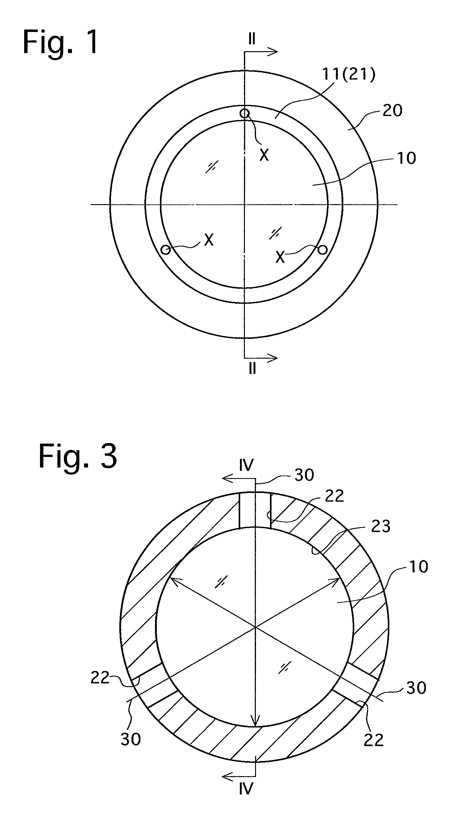
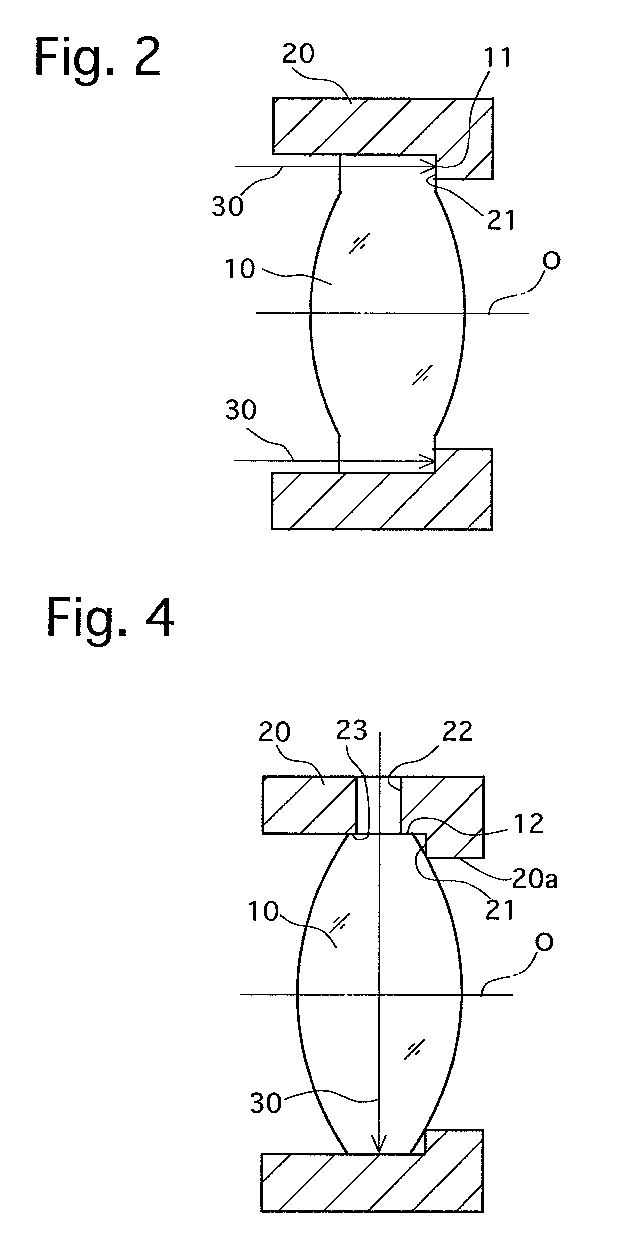
[0026]FIGS. 1 and 2 illustrate a fixing method for a resin lens according to the present invention. A resin lens element 10 is made of amorphous polyolefin, and has a rotationally symmetric shape centered on an optical axis O. A resin lens frame 20 is made of amorphous polyolefin with a carbon material incorporated therein, and is dark in color due to the influence of the carbon material. The resin lens frame 20 also has a rotationally symmetric shape centered on the optical axis O. The outer diameter of the resin lens element 10 and the inner diameter of the resin lens frame 20 (the inner diameter positioned in front of an annular abutting surface (restricting portion) 21) are determined so that the resin lens element 10 fits into the resin lens frame 20. The resin lens element 10 is provided, on the peripheral edge portion thereof, with an annular abutting surface 11 which is orthogonal (normal to) the optical axis O of the resin lens element 10. The resin lens frame 20 is provide...

second embodiment

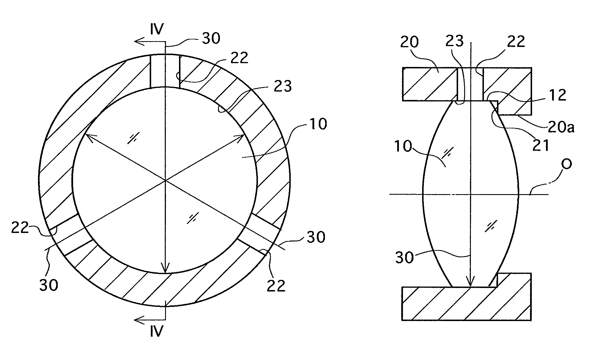
[0031]Note that as shown in FIGS. 3 and 4, in the second embodiment, the laser beam 30 is irradiated in a direction orthogonal to the optical axis O, however, the irradiating direction of the laser beam 30 can be inclined at an angle sharper than 90° without being orthogonal to the optical axis O so long as the laser beam 30 transmits through the irradiation holes 22 and the resin lens element 10 so as to reach the inner circumferential surface (abutting surface) 23 of the resin lens frame 20.

[0032]In the second embodiment, the annular abutting surface (restricting portion) 21 determines the movement extremity of the resin lens element 10 in the optical axis direction thereof (in the right direction in FIG. 4). However, the second embodiment has the advantage of being able to fix the resin lens element 10 to the resin lens frame 20 even if the resin lens element 10 does not abut against the annular abutting surface 21 so long as the irradiation holes 22 and the outer peripheral edge...


PUM


Abstract

A fixing method for a resin lens in which a resin lens element is fixed to a resin lens frame, includes forming the resin lens element and the resin lens frame using amorphous polyolefin as a resin material therefor; forming an abutting surface in each of the resin lens element and the resin lens frame so as to mutually abut against each other; abutting the resin lens element and the resin lens frame mutually against each other at the abutting surfaces thereof; and laser welding the abutting surfaces to each other by irradiating a laser beam thereon.

Description

BACKGROUND OF THE INVENTION[0001]1. Field of the Invention[0002]The present invention relates to a fixing method for a resin lens.[0003]2. Description of the Prior Art[0004]In recent years, mobile devices, such as mobile phones, having a camera installed therein have been increasingly common. In such a camera, it is common practice to fix a lens to a lens frame thereof using a UV adhesive. Specifically, the lens is fixed to the lens frame by irradiating ultraviolet light onto the UV adhesive which as been applied between the lens and the lens frame, and the UV adhesive accordingly is cured by this ultraviolet light.[0005]Since the pixel pitch is small due to the camera provided in a mobile device being very small, the positional precision required in the lens frame when fixing the lens to the lens frame is extremely high.[0006]However, if a UV adhesive is used, when the UV adhesive is being cured, since the UV adhesive contracts, the position of the lens with respect to the lens fra...

Claims


Application Information

Patent Timeline
IPC IPC(8): G02B7/02
CPCB29D11/00009G02B7/02
Inventor SHIMIZU, KUNIHIKOIIKAWA, MAKOTOKOMORI, KAZUNORIMINAMI, KOJI
Owner ZEON CORP
Why Eureka
Try Eureka