Visual acuity testing apparatus

Inactive Publication Date: 2008-10-23
NIDEK CO LTD
View PDF7 Cites 15 Cited by
  • Summary
  • Abstract
  • Description
  • Claims
  • Application Information

AI Technical Summary

Benefits of technology

[0008]An object of the invention is to overcome the problems described above and to provide a visual acuity testing apparatus capable of performing visual acu

Problems solved by technology

This means that tests are performed under different c

Method used


Image

  • Visual acuity testing apparatus
  • Visual acuity testing apparatus
  • Visual acuity testing apparatus

Examples


Embodiment Construction

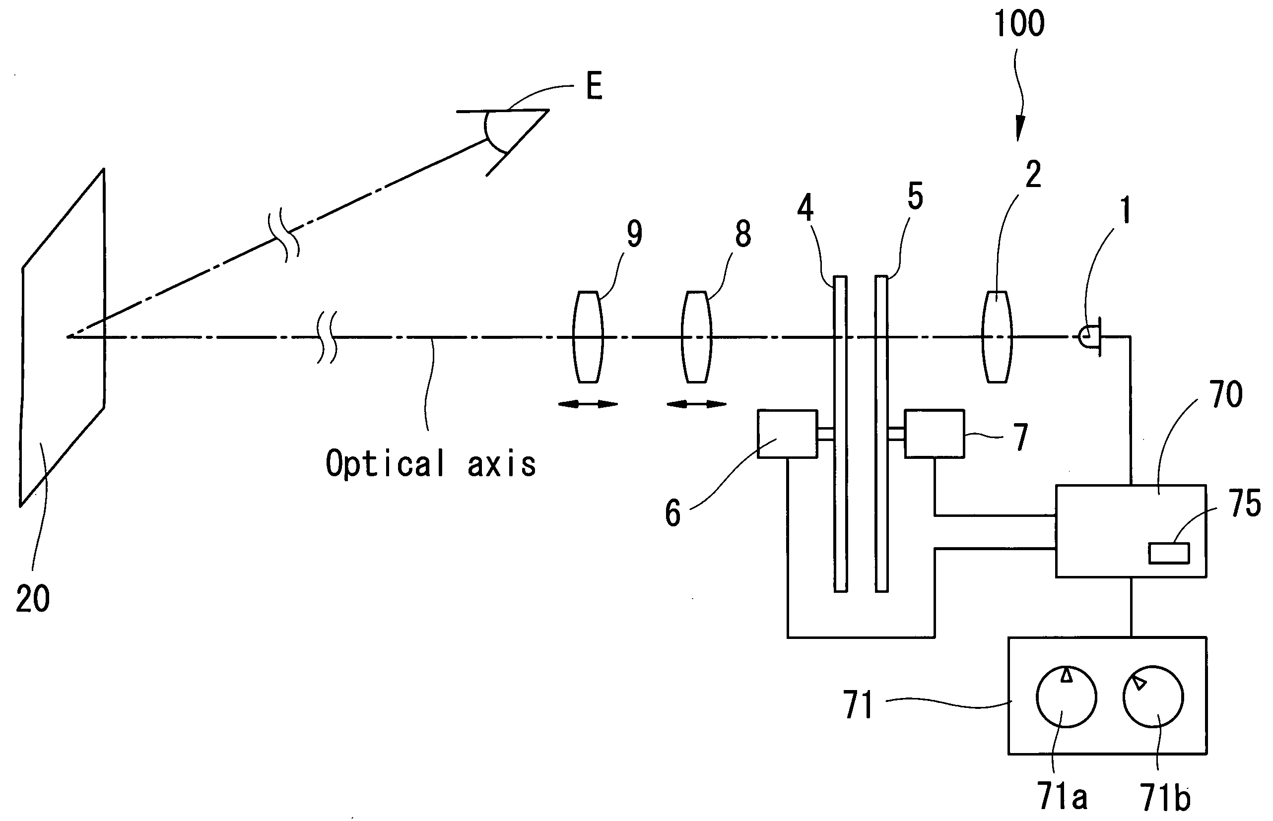
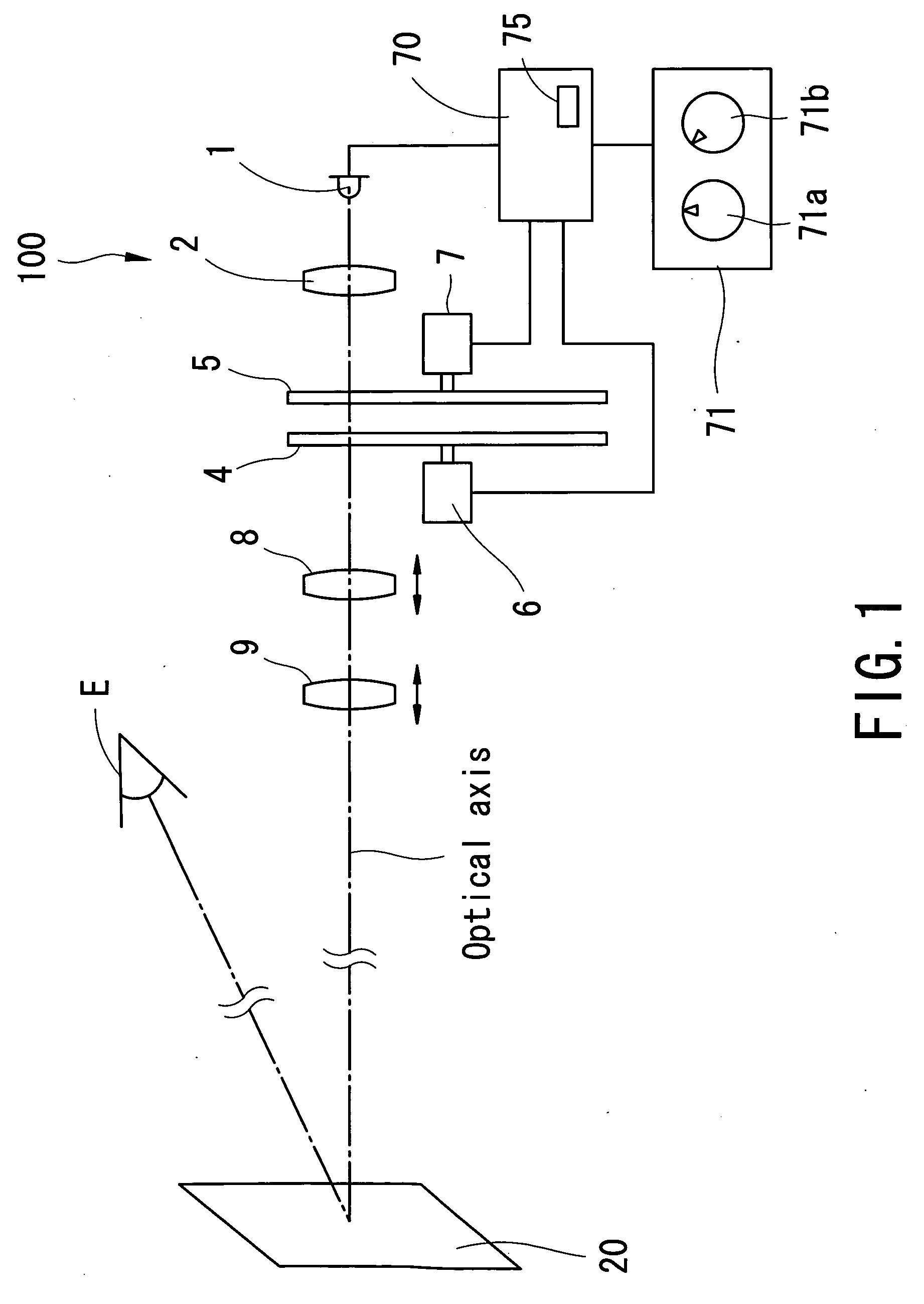
[0015]A detailed description of a visual acuity testing apparatus according to preferred embodiments of the present invention is provided below with reference to the accompanying drawings. FIG. 1 is a schematic view showing a configuration of an optical system and a control system of a projection-type visual acuity testing apparatus (a projection-type chart presenting apparatus) 100.

[0016]A white LED is used as an illumination light source 1. Between a condenser lens 2 and projection lenses 8 and 9, placed are a chart disk 4 and a mask disk 5. The chart disk 4 is a disk plate made of a transparent material such as glass. On a circumference of a circle on the chart disk 4, a plurality of charts is formed by chrome deposition. The charts are illuminated from behind by the illumination light source 1 via the condenser lens 2. The chart disk 4 is rotated by a motor 6, thereby changing types of the charts. The mask disk 5 is used to provide masks such as a vertical line mask, a horizonta...


PUM


Abstract

A visual acuity testing apparatus capable of performing visual acuity testing under substantially uniform conditions even when a test distance and an installation distance vary has a projection optical unit including a disk whereon a chart is placed, an illumination light source, and variable projection lenses which are moved so as to change an image-forming position and an image size of an image of the chart, an input unit into which an installation distance between the screen and the visual acuity testing apparatus and a test distance between the screen and an examinee are inputted, a projection lens driving unit which moves the variable projection lenses based on the installation distance and the test distance, and a light intensity adjusting unit which adjusts light intensity based on the installation distance and the test distance so that brightness of the chart image falls within a predetermined reference range.

Description

BACKGROUND OF THE INVENTION[0001]1. Field of the Invention[0002]The present invention relates to a visual acuity testing apparatus which projects an image of a chart for visual acuity testing onto a screen and tests visual acuity of an examinee's eye.[0003]2. Description of Related Art[0004]Conventionally, there is known a projection-type visual acuity testing apparatus which projects an image of a chart for visual acuity testing onto a screen placed in a position at a predetermined distance (a test distance) from an examinee. In this apparatus, a projection lens is moved in accordance with positions of the screen, the apparatus, and the examinee. In one type of the apparatus, an installation distance (a distance from the screen to the apparatus, also called as a projection distance) and the test distance are equal, and an adjustment is performed so that an image of the chart having a predetermined size corresponding to these distances is projected onto the screen (see Japanese Pate...

Claims


Application Information

Patent Timeline
IPC IPC(8): A61B3/032
CPCA61B3/032A61B3/00A61B3/04
Inventor NOZAWA, NORITSUGUKANAZAWA, YUICHIROSUZUKI, RYOJI
Owner NIDEK CO LTD
Why Eureka
Try Eureka