Control apparatus and control method for aircraft

a control apparatus and control method technology, applied in the direction of aircraft navigation control, machines/engines, transportation and packaging, etc., can solve the problems of unbalanced turbine-engine output, reduced redundancy, reliability, and safety of operation, and achieve the effect of ensuring redundancy and safe operation of twin-engine configuration

Inactive Publication Date: 2007-06-07
TOYOTA JIDOSHA KK
View PDF2 Cites 9 Cited by
  • Summary
  • Abstract
  • Description
  • Claims
  • Application Information

AI Technical Summary

Benefits of technology

[0019] With the control apparatus and control method for an aircraft according to the invention, the multiple gas-turbine engines of the aircraft, which are controlled under condition where a constant pressure ratio is maintained, can evenly produce the output. Thus, the conditions of the gas-turbine engines are kept uniform. As a result, redundancy and safe operation offered by the twin-engine configuration can be ensured.

Problems solved by technology

Accordingly, if the constant pressure ratio control is uniformly performed in the multiple gas-turbine-engines using the same pressure ratio as the target pressure ratio, the outputs from the multiple gas-turbine-engines may not always be uniform.
As a result, the mechanical conditions of the gas-turbine-engines may be unbalanced, which reduces redundancy, reliability, safe operation, etc., namely, the advantages offered by providing multiple gas-turbine-engines.

Method used


Image

  • Control apparatus and control method for aircraft
  • Control apparatus and control method for aircraft
  • Control apparatus and control method for aircraft

Examples


first embodiment

[0049] Because thrust can be controlled in the above-mentioned manner, the gas-turbine-engine 10 is controlled by performing the control for maintaining a constant pressure ratio of the compressed air (hereinafter, referred to as the “constant pressure ratio control”) in the

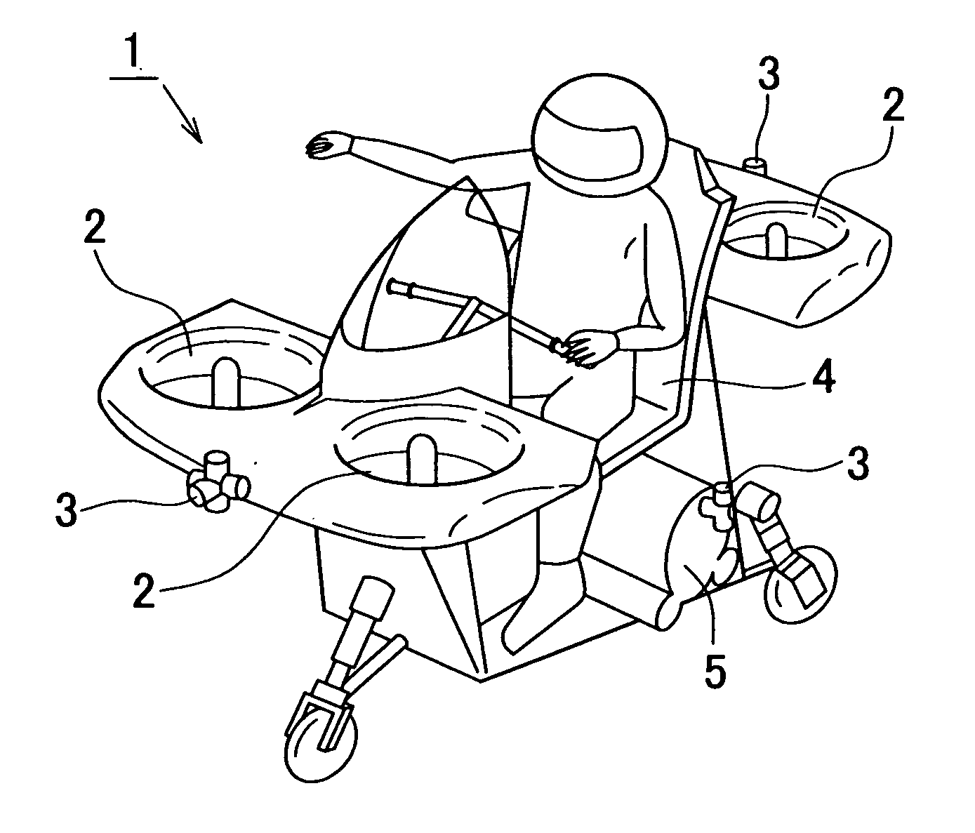
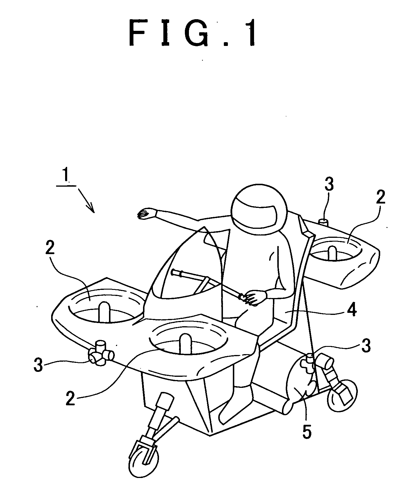
[0050] Attitude of the aircraft 1 is controlled using the nozzles 3, attitude control air pipes 31, and electromagnetically driven valves 32. The air collecting pipe 17 is connected to the four attitude control air pipes 31. The attitude control air pipes 31 are connected to the respective nozzles 3. The electromagnetically driven valve 32, which can change the amount of compressed air flowing through the attitude control air pipe 31, is provided in each of the attitude control air pipes 31. Attitude of the aircraft is changed by changing the combination of the directions in which the compressed air is emitted, using the electromagnetically driven valves 32.

[0051] The electromagnetically driven valves 32 are con...

second embodiment

[0108] Hereafter, the aircraft required output PS_t calculation subroutine will be described with reference to the flowchart in FIG. 15.

[0109] First, in step 151, the engine control ECU 40 detects the output PS_o from the other engine. The engine control unit ECU 40 receives the output control signal indicating the output PS_o transmitted from the other engine control ECU 40.

[0110] In step 152, the engine control ECU 40 calculates the total air flow amount Ga. More specifically, the engine control ECU 40 calculates the total air flow amount Ga based on the operating characteristics of the gas-turbine-engine in FIG. 5, using the current speed N1 of the gas-turbine-engine 10, the pressure ratio P3 / P0, the atmospheric temperature T0, and the atmospheric pressure P0 (Ga←f5(N1, P3 / P0, T0, P0)). The function f5 is used to calculate the total air flow amount Ga corresponding to the speed N1 under the condition where a constant pressure ratio is maintained, based on the operating characte...


PUM


Abstract

The thrust control signal transmitted from the operator of an aircraft is input in both an aircraft control ECU and engine control ECUs that control respective gas-turbine engines such that the engine control ECUs can obtain information concerning the aircraft required output. The engine control ECUs control speeds of the respective gas-turbine engines such that each of the gas-turbine engines half the aircraft required output.

Description

INCORPORATION BY REFERENCE [0001] The disclosure of Japanese Patent Application No. 2005-348828 filed on Dec. 2, 2005 including the specification, drawings and abstract is incorporated herein by reference in its entirety. BACKGROUND OF THE INVENTION [0002] 1. Field of the Invention [0003] The invention relates to a control apparatus and method for controlling thrust and attitude of an aircraft provided with multiple gas-turbine-engines. [0004] 2. Description of the Related Art [0005] An aircraft is usually provided with multiple engines to ensure safe operation even in the event of an engine failure. With this configuration, even if a failure occurs in one or more engines, the aircraft can continue flying using the remaining engine(s) operating properly. [0006] For example, Published Japanese Translation of PCT Application JP-08-502805 describes a technology related to a helicopter provided with two free turbine-engines. According to the technology, when a failure is detected in one...

Claims


Application Information

Patent Timeline
Patent Type & Authority Applications(United States)
IPC IPC(8): B64C15/02
CPCB64C27/20B64C39/026F02C9/00F02K1/002F05D2220/328
Inventor FUKUDA, DAIKI
Owner TOYOTA JIDOSHA KK
Why Eureka
Try Eureka