
Method and apparatus for establishing virtual resilient packet ring (RPR) subrings over a common communications path

a technology of resilient packet ring and subring, which is applied in the direction of electrical equipment, digital transmission, data switching networks, etc., can solve the problems of loss or loss of advantages of multiple virtual switches on the ring

Inactive Publication Date: 2008-10-23
TELLABS OPERATIONS
View PDF12 Cites 26 Cited by
  • Summary
  • Abstract
  • Description
  • Claims
  • Application Information

AI Technical Summary

Problems solved by technology

Therefore, any advantages of the multiple virtual switches on the ring are either lost due to the virtual switches requiring multiple physical links for forming rings, or due to the virtual switches having to wait for access to a single ring.

Method used


Image

  • Method and apparatus for establishing virtual resilient packet ring (RPR) subrings over a common communications path
  • Method and apparatus for establishing virtual resilient packet ring (RPR) subrings over a common communications path
  • Method and apparatus for establishing virtual resilient packet ring (RPR) subrings over a common communications path

Examples


Embodiment Construction

[0012]A description of example embodiments of the invention follows.

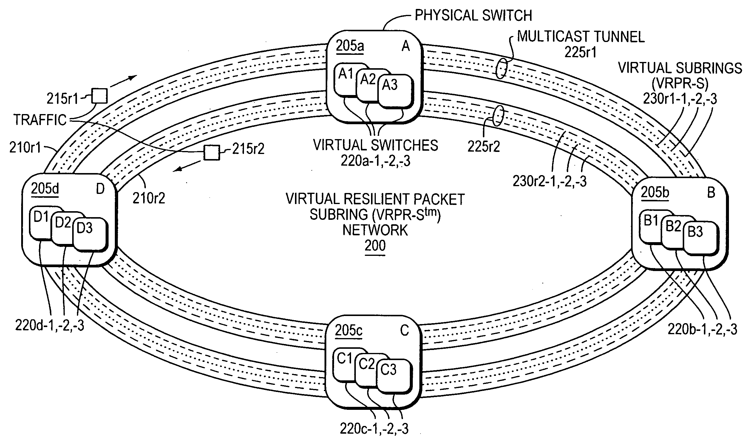
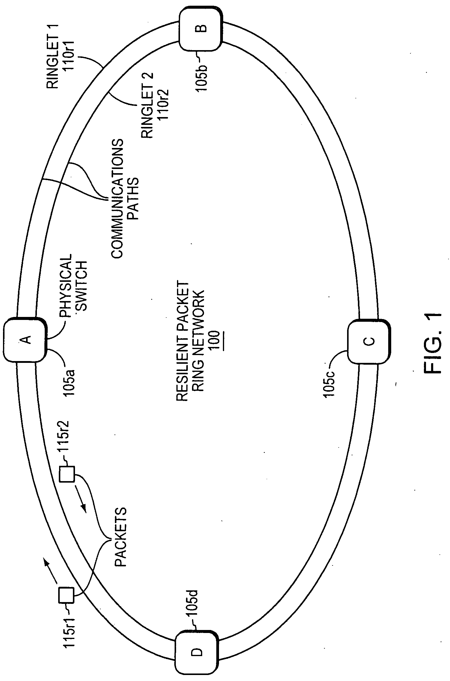
[0013]FIG. 1 is a network diagram of a Resilient Packet Ring (RPR) network (“RPR ring”) 100, also referred to herein simply as a “ring.” The ring 100 has four physical switches 105a-d coupled by two counter-rotating communications paths in this example, Ringlet 1110r1 and Ringlet 2110r2. Traffic 115r1 on Ringlet 1110r1 travels clockwise around the ringlet 110r1, and traffic 115r2 on Ringlet 2110r2 travels counterclockwise around the ringlet 110r2. The terms “traffic” and “communications” are synonymous as used herein. The term “traffic” can be packets or frames, which are also synonymous as used herein.

[0014]Resilient Packet Ring (RPR) in noun form refers to a ring-based network protocol that supports bridging to other network protocols, such as Ethernet. Today's RPR uses 48-bit source and destination Media Access Control (MAC) addresses in the same format as Ethernet. When an Ethernet frame is bridged onto an RPR r...


PUM


Abstract

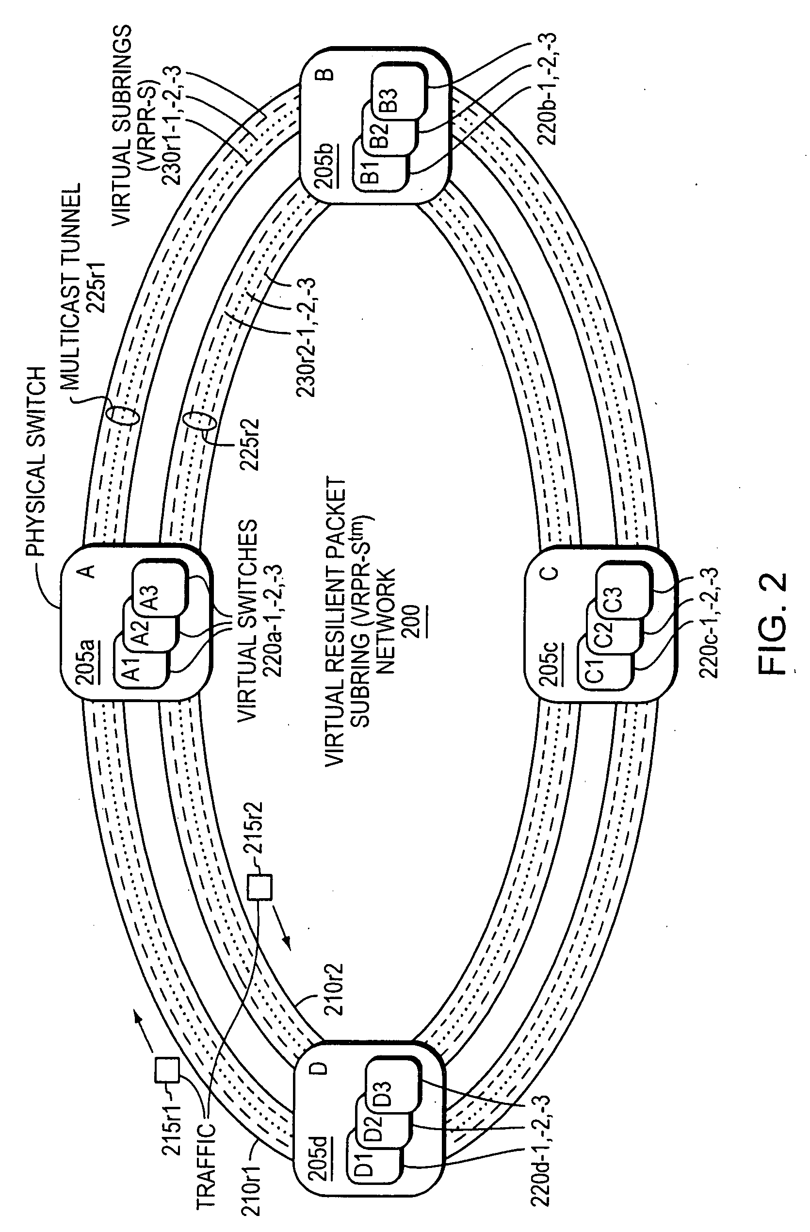
A method and corresponding apparatus allows multiple virtual switches in a physical switch to share one physical Resilient Packet Ring (RPR) in an RPR network. Modules in the multiple virtual switches add multicast information to traffic to direct the traffic along a common path to other physical switches on the ring, and modules in the virtual switches inspect traffic to determine whether the traffic is directed to the respective virtual switch. Multiple virtual RPR subrings are made available in a single physical ring, increasing usefulness of virtual switches formerly only able to support multiple tributary connections to other networks but not able to share a single ring network communications path. Sharing a single communications path increases overall network bandwidth, and at least one implementation allows for spatial reuse.

Description

BACKGROUND OF THE INVENTION[0001]A switch may be logically partitioned into a number of virtual switches, each functioning as an independent switch. Such partitioning of a physical switch may be done for the purpose of segregating traffic, much like a partitioned server where one physical server runs multiple virtual machines. For example, virtual switches may be created within physical switches of a ring network to separate different client networks that may be connected to the physical switches; however, each virtual switch requires its own link to another node on the ring network. Therefore, any advantages of the multiple virtual switches on the ring are either lost due to the virtual switches requiring multiple physical links for forming rings, or due to the virtual switches having to wait for access to a single ring.SUMMARY OF THE INVENTION[0002]According to one example embodiment of the present invention, a ring network may have multiple physical switches configured with multi...

Claims


Application Information

Patent Timeline
Patent Type & Authority Applications(United States)
IPC IPC(8): H04L12/56
CPCH04L12/437H04L12/4641
Inventor CHENG, WEIYINGZETTINGER, CHRIS R.MORAN, MICHAEL T.BUESCHER, GILBERT A.STODDARD, KIMBERLY A.
Owner TELLABS OPERATIONS
Learn More