
Image stabilization with adaptive shutter control

a shutter control and image stabilization technology, applied in the field of image stabilization with adaptive shutter control, can solve the problems of image blur, image blurring, and small cameras such as cell phone cameras are particularly prone to camera shake, and achieve the effect of convenient image stabilization, small size and less cos

Inactive Publication Date: 2008-10-23
AVAGO TECH WIRELESS IP SINGAPORE PTE
View PDF8 Cites 23 Cited by
  • Summary
  • Abstract
  • Description
  • Claims
  • Application Information

AI Technical Summary

Benefits of technology

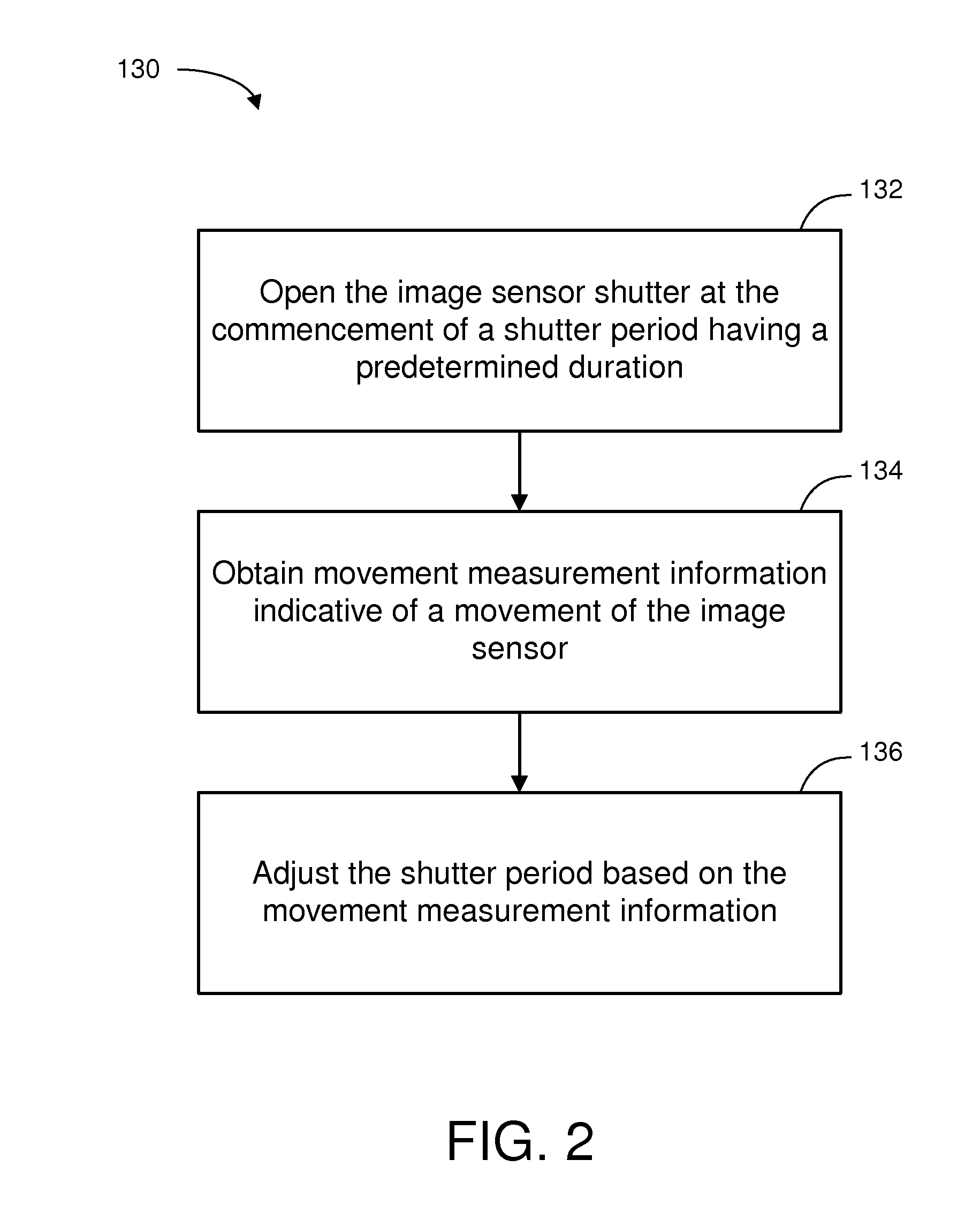
"The patent describes an apparatus and method for image stabilization using adaptive shutter control. The apparatus includes an image sensor, movement detector, and shutter controller. The movement detector measures movement during a shutter period and the shutter controller adjusts the shutter period based on the movement measurement. This allows the image sensor to be responsive to light for a longer period of time, resulting in smoother and more stable images. The technical effect of this invention is a smaller and less costly implementation for image stabilization."

Problems solved by technology

Image blur is a common problem in photography and has a variety of causes such as focusing errors and motion of the imaged object.
When a person is holding a camera during exposure, camera shake causes image blurring, particularly during long exposure times and for image enlargement (e.g., using a zoom or telephoto lens).
Additionally, small cameras such as cell phone cameras are particularly prone to camera shake because they are constructed of lightweight materials and are sometimes awkward to hold during operation.
However these conventional mechanical systems are cost prohibitive and are often too large to be implemented in small camera systems such as cell phone cameras.
Additionally, conventional mechanical systems are subject to mechanical failures.

Method used


Image

  • Image stabilization with adaptive shutter control
  • Image stabilization with adaptive shutter control
  • Image stabilization with adaptive shutter control

Examples


Embodiment Construction

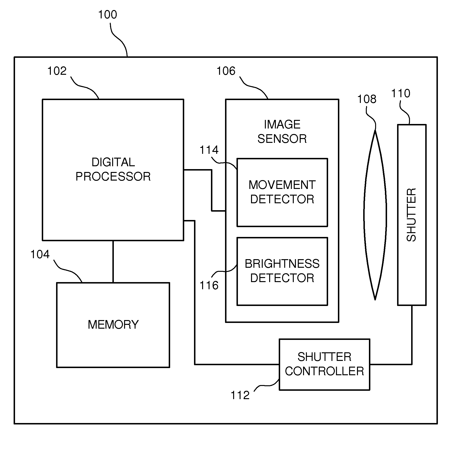
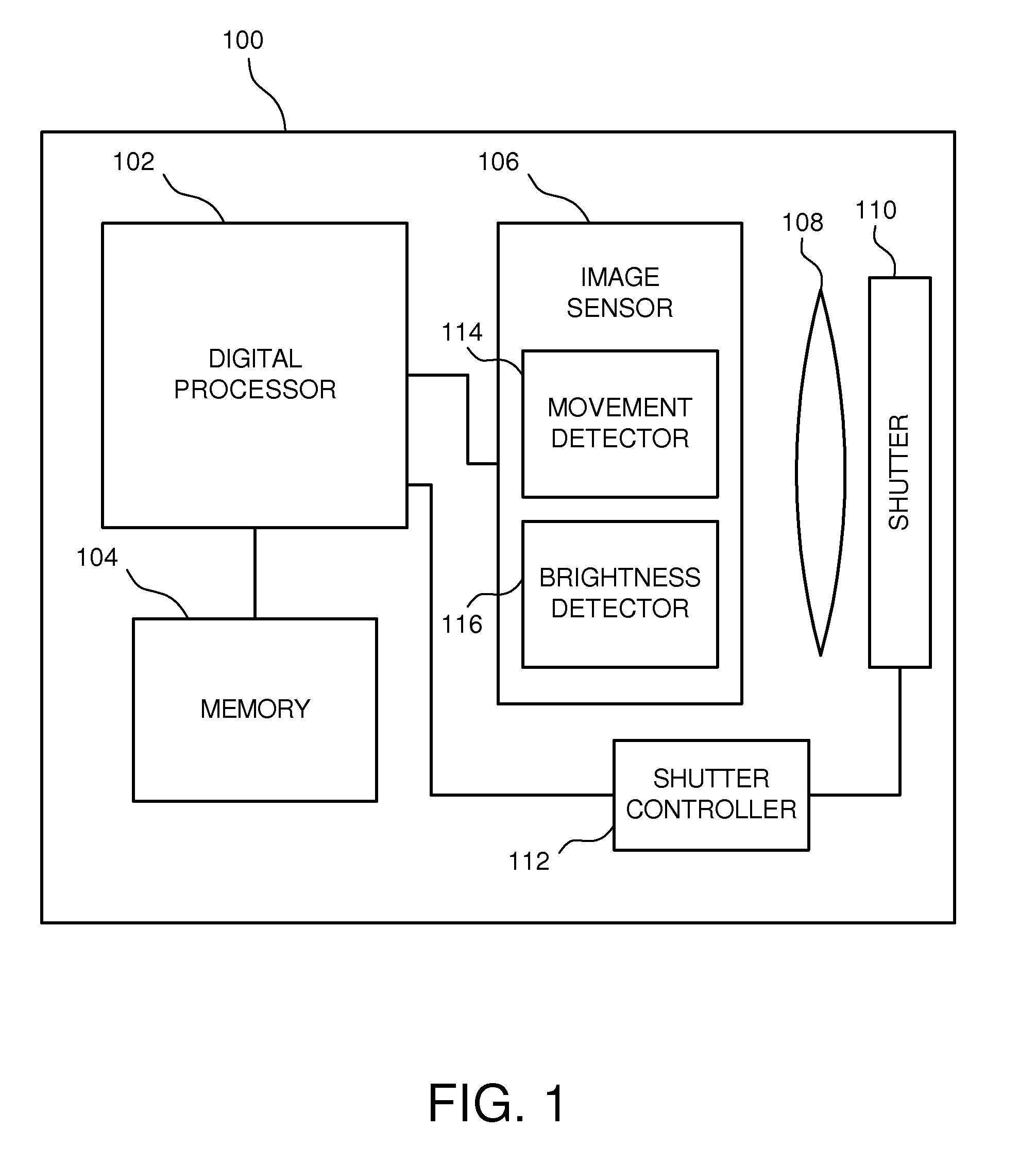
[0021]FIG. 1 depicts a schematic diagram of one embodiment of a camera system 100. The depicted camera system 100 includes a digital processor 102, an electronic memory device 104, an image sensor 106, a lens 108, a shutter 110, and a shutter controller 112. Although the various elements of the camera system 100 are shown in a particular arrangement, it should be noted that the depicted configuration is merely schematic and other embodiments may implement arrangements that are different from what is shown in FIG. 1. Additionally, some embodiments of the camera system 100 may include fewer or more elements than are shown in FIG. 1 and described below.

[0022]In one embodiment, the digital processor 102 facilitates execution of various instructions and operations which impart functionality to the camera system 100. These instructions may be stored within the digital processor 102, in the memory 104, or in another memory device within or coupled to the camera system 100. The memory 104 a...


PUM


Abstract

An apparatus to facilitate image stabilization with adaptive shutter control is described. An embodiment of the apparatus includes an image sensor, a movement detector, and a shutter controller. The movement detector is coupled to the image sensor. The shutter controller is coupled to the movement detector. The image sensor is configured to obtain image data. The movement detector is configured to obtain movement measurement information during a shutter period having a predetermined duration. The shutter controller is configured to adjust the shutter period of a shutter based on the movement measurement information. The shutter controls the time the image sensor is responsive to light incident on the image sensor. Embodiments of the apparatus provide a smaller and less costly implementation for image stabilization.

Description

BACKGROUND OF THE INVENTION[0001]Image blur is a common problem in photography and has a variety of causes such as focusing errors and motion of the imaged object. Motion of the camera relative to the imaged object is another source of image blur. Camera motion is also referred to as camera shake or hand shudder. When a person is holding a camera during exposure, camera shake causes image blurring, particularly during long exposure times and for image enlargement (e.g., using a zoom or telephoto lens). Camera shake is typical because human muscles naturally tremor at frequencies approximately in the range of 4-12 Hz. Additionally, small cameras such as cell phone cameras are particularly prone to camera shake because they are constructed of lightweight materials and are sometimes awkward to hold during operation.[0002]In efforts to reduce image blur, imaging devices such as hand-held cameras typically implement some type of image stabilization technology. Image stabilization refers ...

Claims


Application Information

Patent Timeline
Patent Type & Authority Applications(United States)
IPC IPC(8): G03B17/00
CPCH04N5/23248H04N5/23251H04N5/2353H04N23/681H04N23/68H04N23/73
Inventor BROSNAN, MICHAEL JOHNSCHNEIDER, ALEXANDERWILSON, ROBERT
Owner AVAGO TECH WIRELESS IP SINGAPORE PTE
Learn More