
Calendar Board Which Distinguishes the Holiday and the Normal Day

Inactive Publication Date: 2008-10-30
KWON MYEONG I
View PDF12 Cites 14 Cited by
  • Summary
  • Abstract
  • Description
  • Claims
  • Application Information

AI Technical Summary

Benefits of technology

[0006]Accordingly, the present invention has been made to solve the above-mentioned problems occurring in the prior art, and it is an object of the present invention to provide a calendar board capable

Problems solved by technology

However, such board and calendar also have some disadvantages in that additional space for storing unused date blocks therein is needed, and in that it is possible to frequently loss the date blocks since the unused date blocks are stored in additional space.

Method used


Image

  • Calendar Board Which Distinguishes the Holiday and the Normal Day
  • Calendar Board Which Distinguishes the Holiday and the Normal Day
  • Calendar Board Which Distinguishes the Holiday and the Normal Day

Examples


second embodiment

[0038]FIG. 7 is an exploded perspective view showing a date block according to another embodiment of the present invention, and FIG. 8 is a view showing a used state of the date block according to the present invention.

[0039]As shown in the drawings, the date block 200 according to the second embodiment of the present invention is a magnet having a number on both sides thereof, and includes an isotropic rubber magnet 210, an anisotropic rubber magnet 220, and bonding means 240 for bonding the rubber magnets with each other.

[0040]The isotropic rubber magnet 210 is a common magnet which is generally used as stationery articles and simply attached on something without strong magnetic force or precision. Such isotropic rubber magnet is manufactured by a press process after adding magnetic powder particle, such as ferrite powder, with rubber material.

[0041]The anisotropic rubber magnet 220 is manufactured by giving a uniform directionality to ferrite powder particles, which are mixed wit...

third embodiment

[0049]As shown in FIG. 9, in the present invention, the date block 200 is a magnetic body which can be bonded on not only a magnetic board but also a general board 260, and includes a magnetic plate 250 disposed on the rear surface thereof. The magnetic plate 250 includes a bonded portion 252 having a release paper 251 so as to be bonded on the general board 260. The bonded portion 252 is bonded on the rear surface of the magnetic plate 250, and double-coated adhesive tape or adhesives may be coated thereon. The release paper 251 is disposed on the rear surface of the bonded portion 252 in order to prevent lowering of bonding force of the bonded portion 252 or damage of the bonded portion 252.

[0050]FIG. 11 is a perspective view showing a package for assembling the date blocks according to the present invention.

[0051]As shown in FIG. 11, the package 270 includes the isotropic rubber magnet 210 and the anisotropic rubber magnet 220 having the indication parts 230, and the bonding mean...


PUM


Abstract

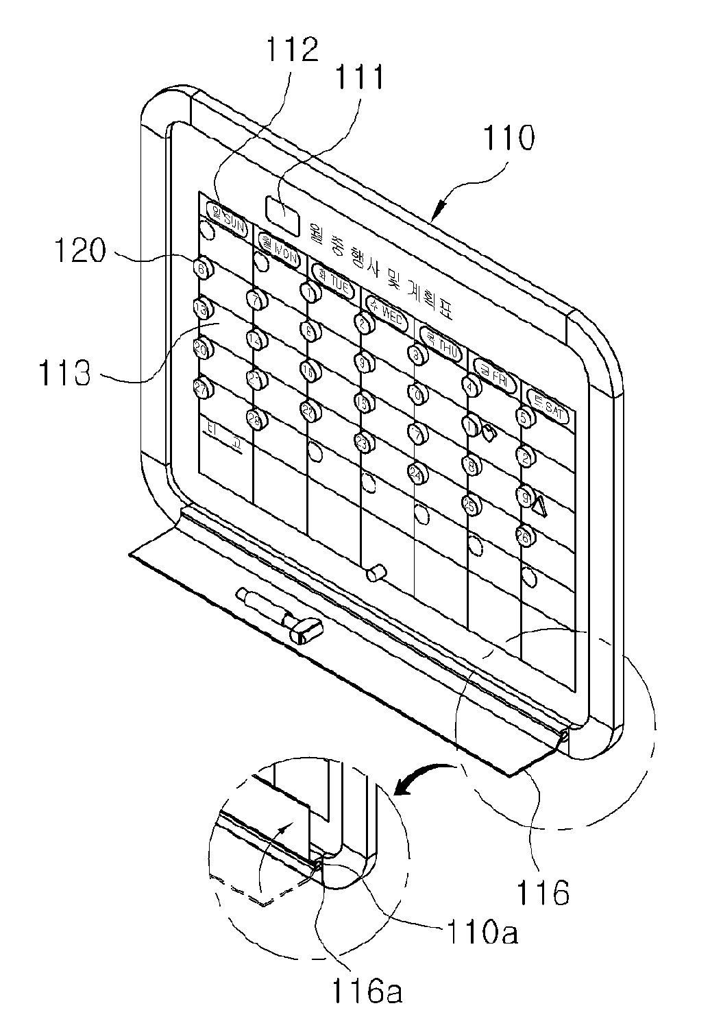
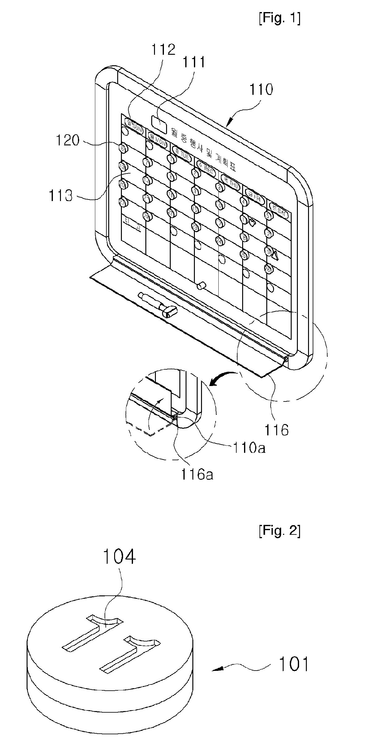
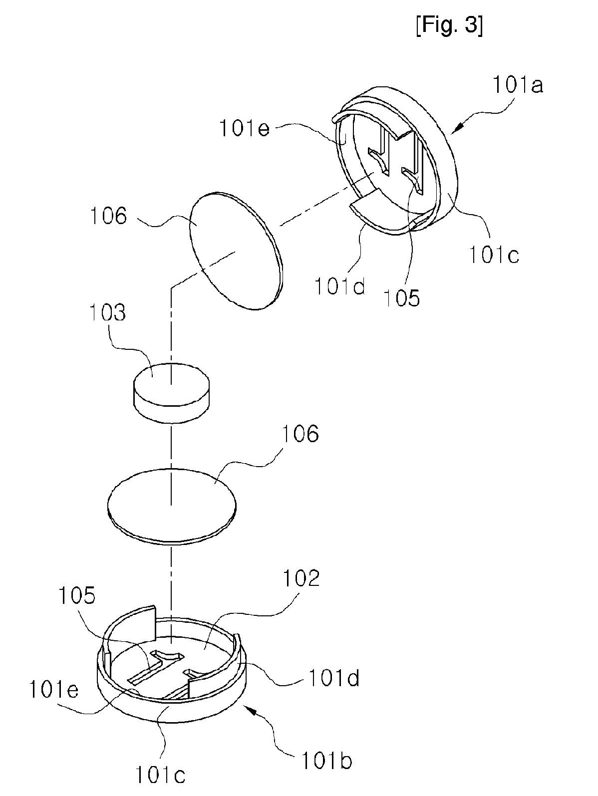
Disclosed therein is a calendar board capable of distinguishing a holiday and an ordinary day with one block. The calendar board includes: a board body in which a magnetic body is embedded and on which a date table is printed, the date table having a month indication section located on the front surface of the board body, an array of day sections located beneath the month indication section for dividing days, arrays of date sections located beneath the array of day sections, and a memo section having a space for allowing a user to take a memo; and thirty-one date blocks respectively bonded on an edge of the upper portion of each section of the arrays of date sections, each date block having two colors printed on both sides thereof for distinguishing a holiday and an ordinary day, each date block being smaller than the memo section formed on the date dividing table. The calendar board can easily distinguish a holiday and an ordinary day by indicating the same date on both sides of one date block with different colors, and prevent inconvenience to use a marker pen since the date block can be detachably attached on the board by using a magnet.

Description

TECHNICAL FIELD[0001]The present invention relates to a calendar board capable of distinguishing a holiday and an ordinary day with one block, and more particularly, to a block used for realizing a perpetual calendar on a writable board, which has magnetic force and expresses the same date indicated on both sides of the block with different colors, thereby distinguishing a holiday and an ordinary day with one with one block.BACKGROUND ART[0002]In general, a board for realizing a perpetual calendar using magnets having a date thereon serves as the perpetual calendar in such a way that rubber magnets, each of which has a date printed on one side thereof, are bonded on edges of sections divided at regular intervals while locations of the rubber magnets are changed whenever the month is changed.[0003]However, such calendar board has several disadvantages in that a user cannot clearly distinguish holidays and ordinary days at a look since the dates written on the magnets are all colored ...

Claims


Application Information

Patent Timeline
IPC IPC(8): G09D3/02
CPCB43L1/008G09D3/04G09F7/04
Inventor KWON, MYEONG-I
Owner KWON MYEONG I
Learn More