
Method, system, program, and data structures for mapping logical blocks to physical blocks

a technology of logical blocks and data structures, applied in the field of system, method, program, data structure for mapping logical blocks to physical blocks, can solve the problems of not being able to dynamically increase the size of a volume currently in use, and the administrator of the system is limited to the size of freed-up spa

Inactive Publication Date: 2005-01-04
IBM CORP
View PDF11 Cites 152 Cited by
  • Summary
  • Abstract
  • Description
  • Claims
  • Application Information

AI Technical Summary

Benefits of technology

Preferred embodiments provide a method, system, program, and data structures for defining logical and physical storage as groups of chunks in a manner such that physical chunks at non-contiguous storage locations may be associated with contiguous logical chunks. In this way, the size of the logical volume can be expanded by associating further physical chunks, without regard to where those physical chunks are located in storage, with logical chunks contiguous to the current set of logical chunks defining the logical volume. By defining a storage system including multiple storage devices into physical chunks physical chunks from different storage devices and raid arrays, contiguous and non-contiguous chunks in the same logical volume may be associated with physical chunks in different RAID arrays. This allows for dynamic management of space allocated to logical volumes.

Problems solved by technology

One drawback of this approach is that the Logical Volume Managers on different host systems must coordinate their activity to ensure that they all maintain the same assignment of logical chunks of the LUN to the logical volumes.
Thus, the systems administrator is limited to the size of the freed-up space in attempting to reuse that space for another logical volume.
Further, in prior host systems that do not include the Logical Volume Manager, there is no way to dynamically increase the size of a volume that is currently in use.

Method used


Image

  • Method, system, program, and data structures for mapping logical blocks to physical blocks
  • Method, system, program, and data structures for mapping logical blocks to physical blocks
  • Method, system, program, and data structures for mapping logical blocks to physical blocks

Examples


Embodiment Construction

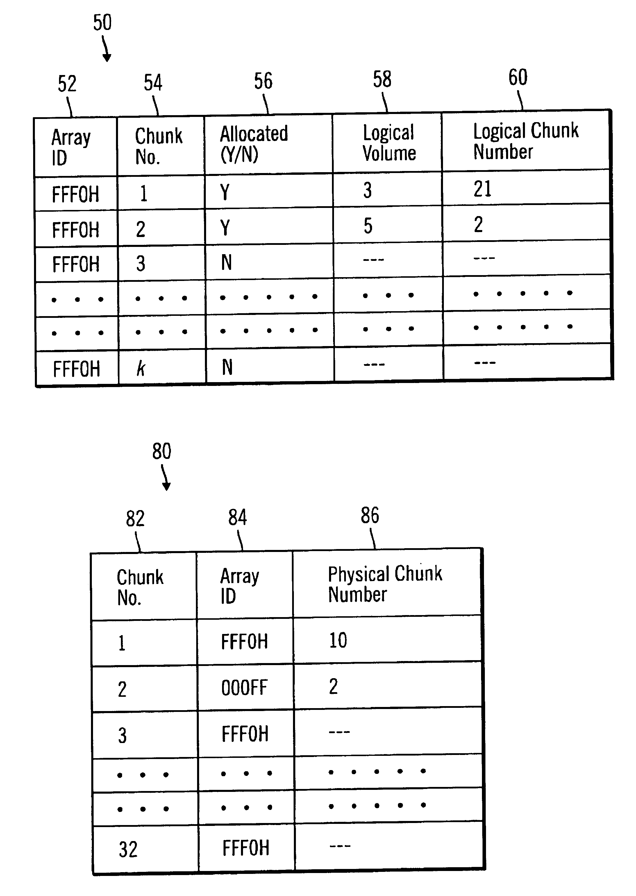
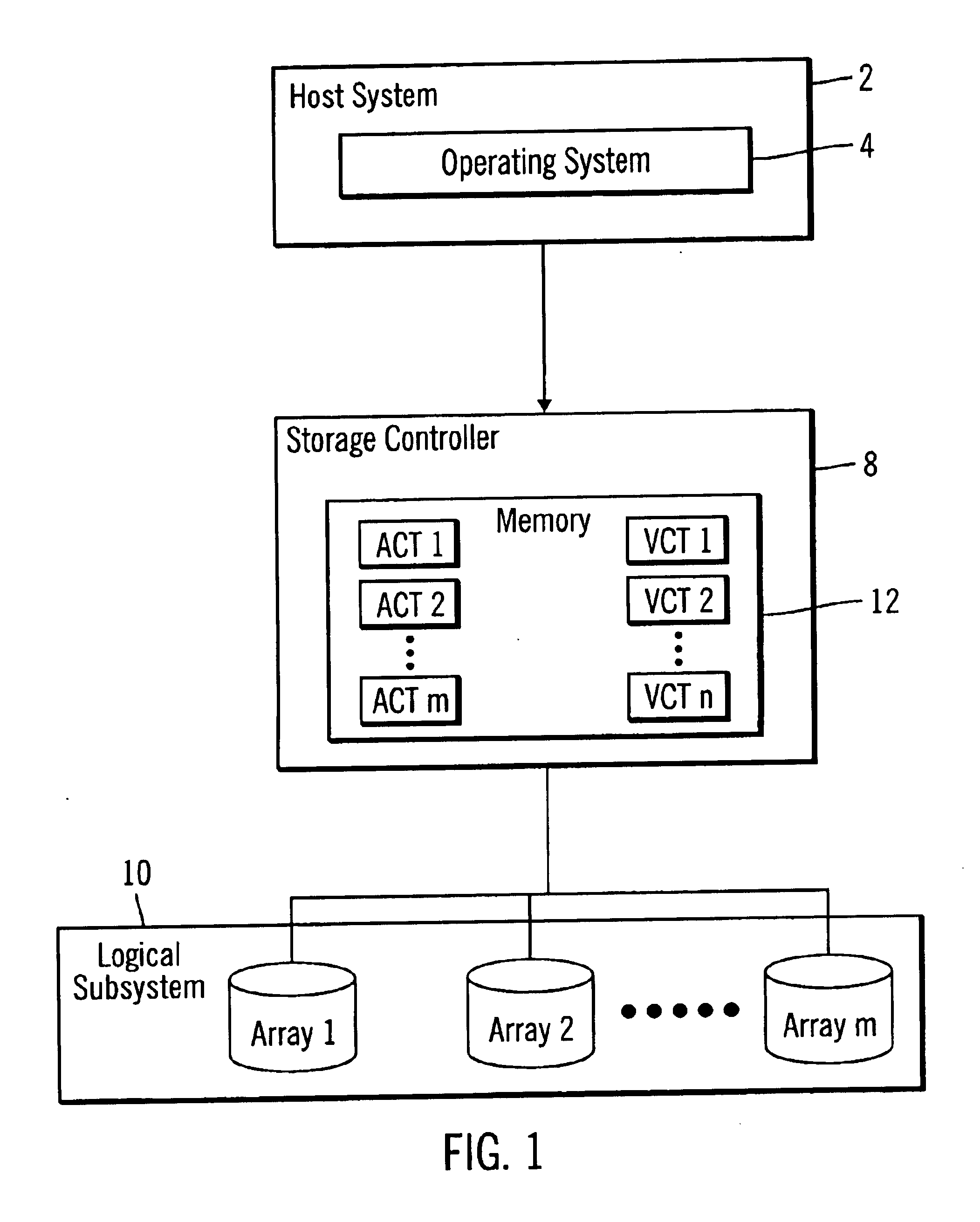
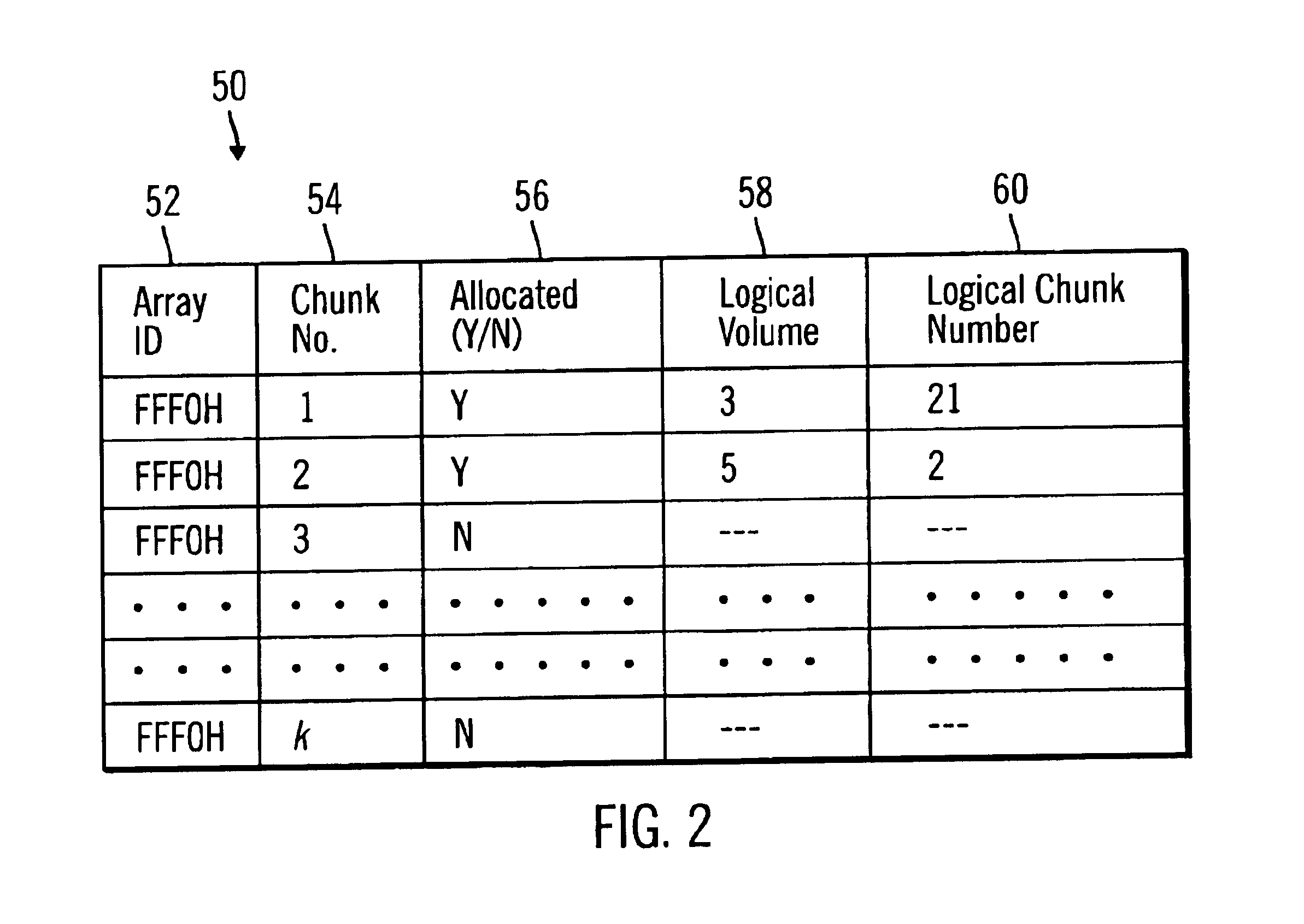
To overcome the limitations in the prior art described above, preferred embodiments disclose a method, system, program, and data structure for a storage controller to map logical blocks to physical storage blocks. The storage controller is in communication with at least one host system that views a logical storage space. The storage controller defines the logical storage space as a sequence of logical chunks, wherein each logical chunk comprises a plurality of logical blocks in the logical storage space. The storage controller further defines a physical storage space as a sequence of physical chunks, wherein each physical chunk comprises a plurality of physical blocks in the physical storage system. The storage controller associates each logical chunk in the sequence of logical chunks defining the logical storage space with one physical chunk in the physical storage system. Further, the contiguous logical chunks are capable of being associated with non-contiguous physical chunks.

In ...


PUM


Abstract

Disclosed is a method, system, program, and data structure for a storage controller to map logical blocks to physical storage blocks. The storage controller is in communication with at least one host system that views a logical storage space. The storage controller defines the logical storage space as a sequence of logical chunks, wherein each logical chunk comprises a plurality of logical blocks in the logical storage space. The storage controller further defines a physical storage space as a sequence of physical chunks, wherein each physical chunk comprises a plurality of physical blocks in the physical storage system. The storage controller associates each logical chunk in the sequence of logical chunks defining the logical storage space with one physical chunk in the physical storage system. Further, the contiguous logical chunks are capable of being associated with non-contiguous physical chunks.

Description

BACKGROUND OF THE INVENTION1. Field of the InventionThe present invention relates to a system, method, program, and data structures for mapping logical blocks to physical blocks by defining logical chunks and physical chunks in the logical and physical storage spaces, respectively.2. Description of the Related ArtAn operating system arranges the storage space of a storage system into logical volumes. A hierarchy of structures is used to manage fixed-disk storage. In large mainframe systems, such as the International Business Machines Corporation (IBM) AIX ad, or OS / 390 operating systems, each individual fixed-disk drive is referred to as a physical volume (PV). Every physical volume in use belongs to a volume group (VG). All of the physical volumes in a volume group may be divided into physical partitions (PPs) of the same size. Within each volume group, one or more logical volumes (LVs) are defined. Logical volumes are groups of information located on physical volumes. Data on logi...

Claims


Application Information

Patent Timeline
Patent Type & Authority Patents(United States)
IPC IPC(8): G06F12/10G06F12/00G06F3/06
CPCG06F3/0605G06F3/0689G06F3/064
Inventor BEARDSLEY, BRENT CAMERONKALOS, MATTHEW JOSEPH
Owner IBM CORP
Learn More