Vibrating fishing lure

a technology of vibrating and fishing lures, applied in the field of fishing lures, can solve the problems of not providing the combined benefits of a chatter bait lure and a spinner bait lur

Inactive Publication Date: 2008-10-30
ALBRECHT RUDY S +1
View PDF20 Cites 16 Cited by
  • Summary
  • Abstract
  • Description
  • Claims
  • Application Information

AI Technical Summary

Problems solved by technology

While these and other lures may be suitable for their intended purpose, none provides the combined benefits of a chatter bait lure and a spinner bait lure.

Method used


Image

  • Vibrating fishing lure
  • Vibrating fishing lure
  • Vibrating fishing lure

Examples


Embodiment Construction

[0019]While this invention may be embodied in many forms, there is shown in the drawings and will herein be described in detail one or more embodiments with the understanding that this disclosure is to be considered an exemplification of the principles of the invention and is not intended to limit the invention to the illustrated embodiments.

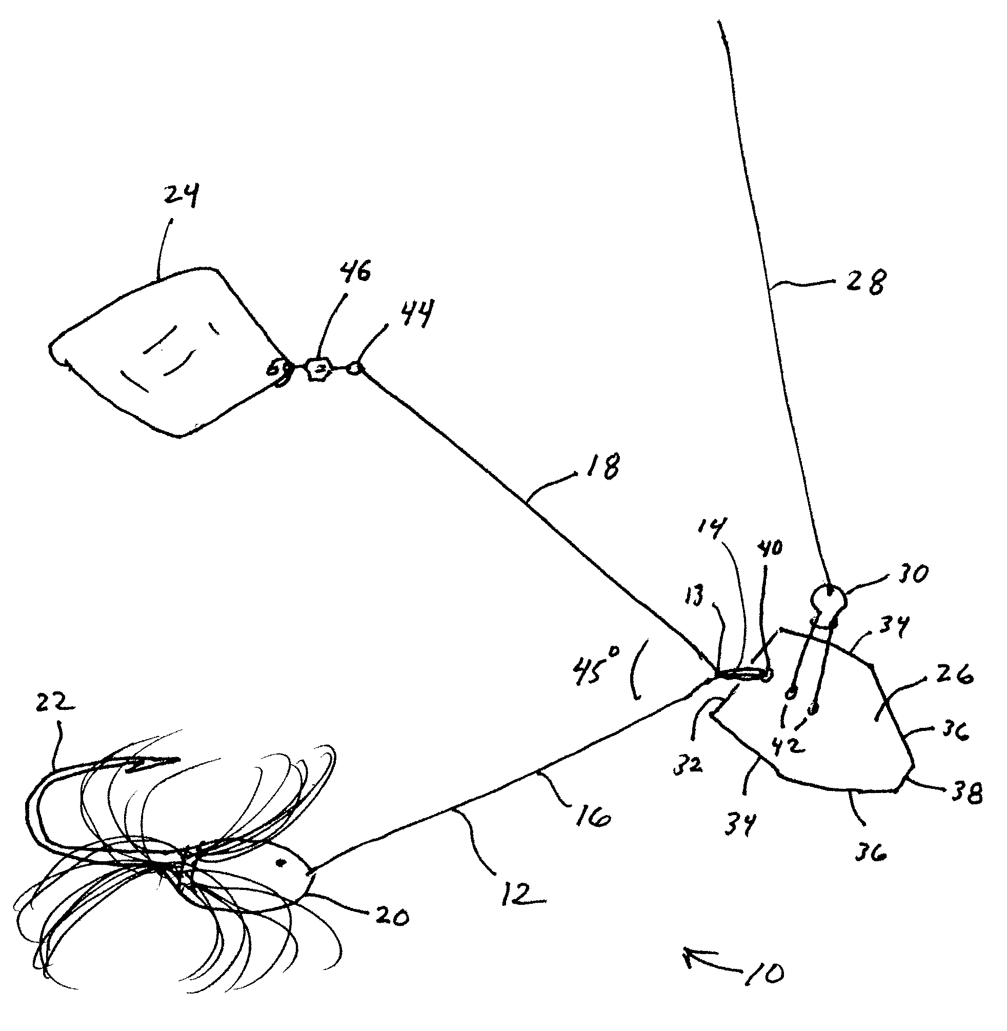
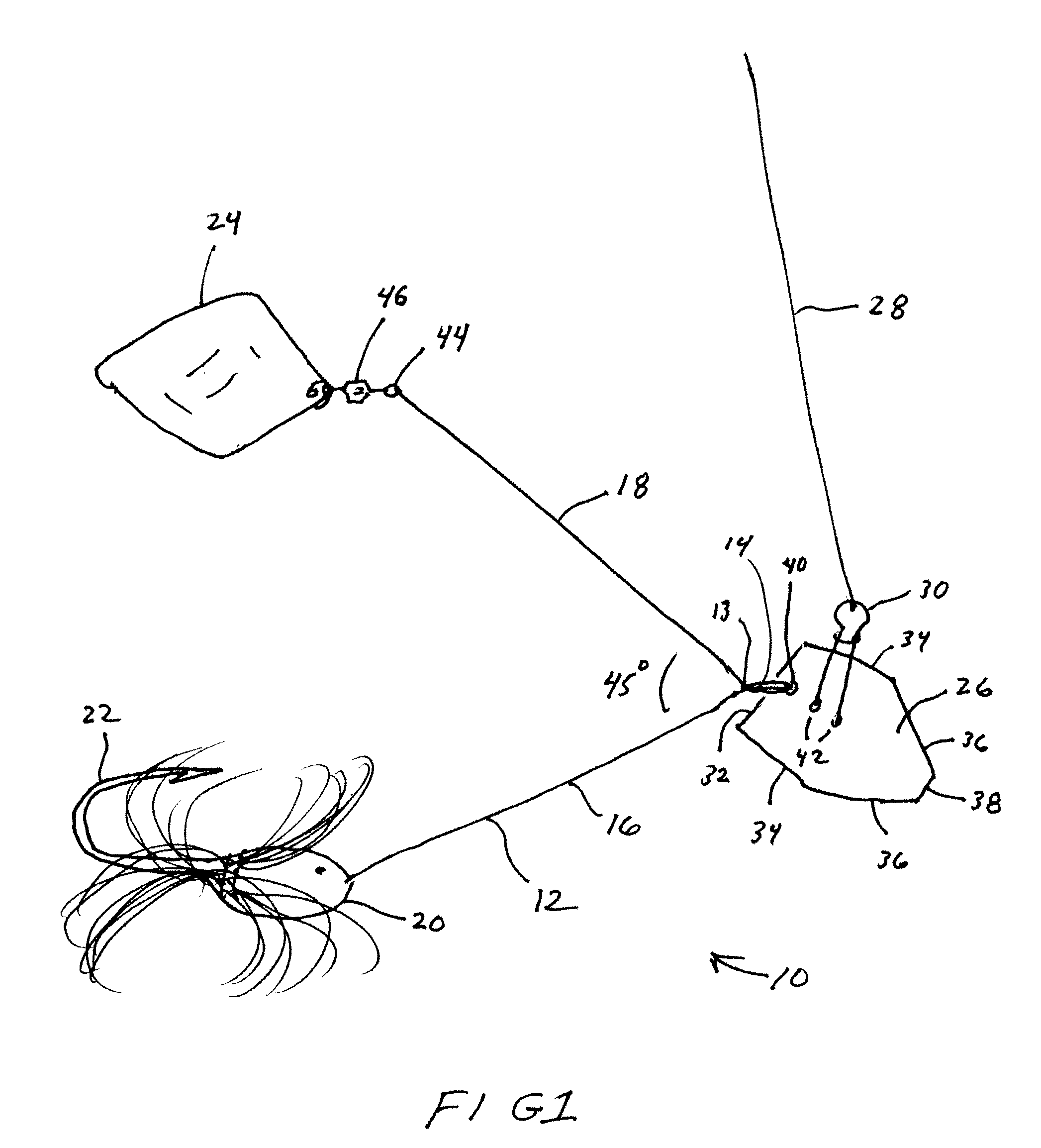
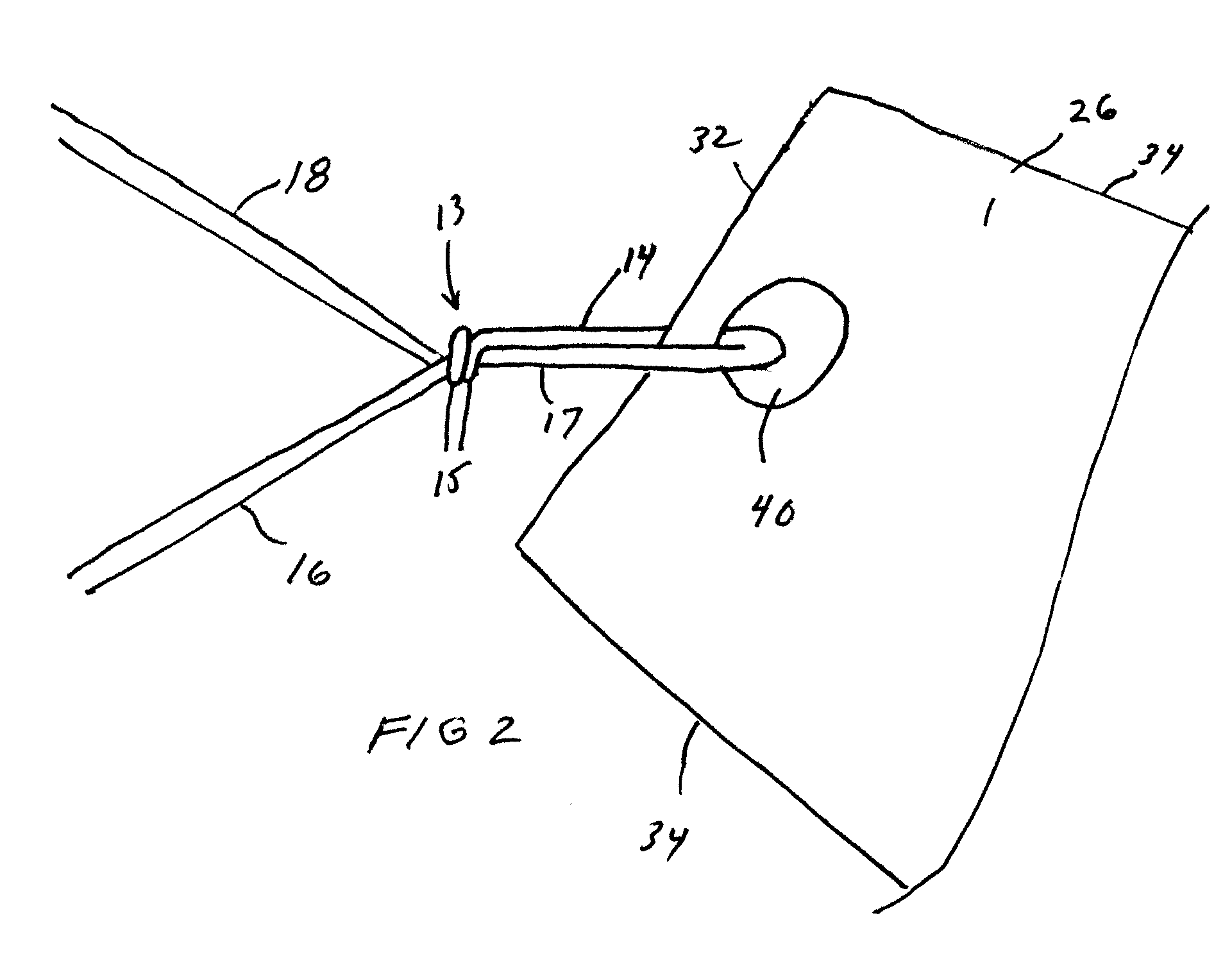
[0020]Turning to the drawings, there is shown in FIGS. 1 and 2 one embodiment of the present invention, a novel fishing lure 10 combining the advantages of a chatter bait lure and a spinner bait lure. The lure 10 comprises a substantially V-shaped wire 12 having an eye loop 14 at its apex and first and second arms 16, 18 extending from the eye loop 14. A jig head 20 having a fishhook 22 projecting therefrom is attached to the distal end of one arm 16. A spinner blade 24 is attached to the distal end of the second arm 18.

[0021]In an important aspect of the invention, a second blade 26 is attached to the eye loop 14 to impart a vibrating motion to...


PUM


Abstract

A fishing lure comprising a substantially V-shaped wire having an eye loop at its apex and first and second arms extending from the eye loop. A jig head having a fishhook projecting therefrom is attached to the end of one arm. A spinner blade is attached to the end of the other arm. A second blade is attached to the eye loop to impart a vibrating motion to the lure.

Description

BACKGROUND[0001]1. Field of the Invention[0002]This patent relates to a fishing lure. More particularly, this patent relates to a fishing lure having a blade that imparts a vibrational effect to the lure to entice fish.[0003]2. Description of the Related Art[0004]Numerous fishing lures have been developed over the years in attempts to attract, and thus catch, more game fish. Some of the more popular lure styles include jigs, jerk baits, crank baits, chatter baits and spinner baits.[0005]A jig is a type of fishing lure comprising a lead sinker or head with a hook extending out of it. The fishing line attaches directly to an eyelet on the head. Jigs often have a plastic or rubber body attached to the head and shaped to resemble a frog, fish, lizard, bug or other live bait. It is common to place on the hook a plastic trailer or other type of trailer to simulate live bait. Jigs come in a variety of weights, from ⅛ of an ounce or less to 1.5 ounces or more.[0006]A jerk bait is a lure hav...

Claims


Application Information

Patent Timeline
Patent Type & Authority Applications(United States)
IPC IPC(8): A01K85/10A01K85/00
CPCA01K85/00A01K85/10
Inventor ALBRECHT, RUDY S.FRANZEN, KARL
Owner ALBRECHT RUDY S
Why Eureka
Try Eureka