Printed border

a technology of printed borders and floor panels, applied in the direction of flooring, transportation and packaging, cellulosic plastic layered products, etc., can solve the problems of paper cores left exposed and unprotected, tire loosening and falling off, maintenance problems,

Inactive Publication Date: 2008-10-30
KINGSPAN HLDG (IRL) LTD
View PDF25 Cites 63 Cited by
  • Summary
  • Abstract
  • Description
  • Claims
  • Application Information

AI Technical Summary

Problems solved by technology

These trims tend to become loose and fall off and become a maintenance problem.
Disadvantages experienced from such routed edges stem from the paper core left exposed and unprotected against cleaners and moisture, and the recessed groove acts as a dirt and moisture trap.
However, it is generally difficult to control the burning process accurately and accordingly such process sometimes burn through the decorative layer and sometimes does not totally remove the clear protective layer resulting in the applied paint wearing off.

Method used


Image

  • Printed border
  • Printed border
  • Printed border

Examples


Embodiment Construction

[0022]In the description that follows, like parts are marked throughout the specification and the drawings with the same respective reference numerals. The drawings are not necessarily to scale and in some instances proportions may have been exaggerated in order to more clearly depict certain features of the invention.

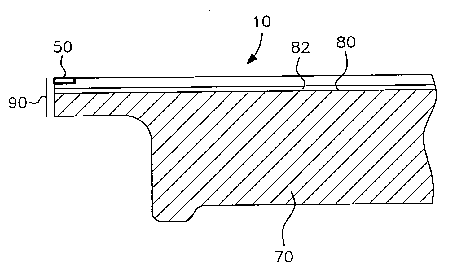
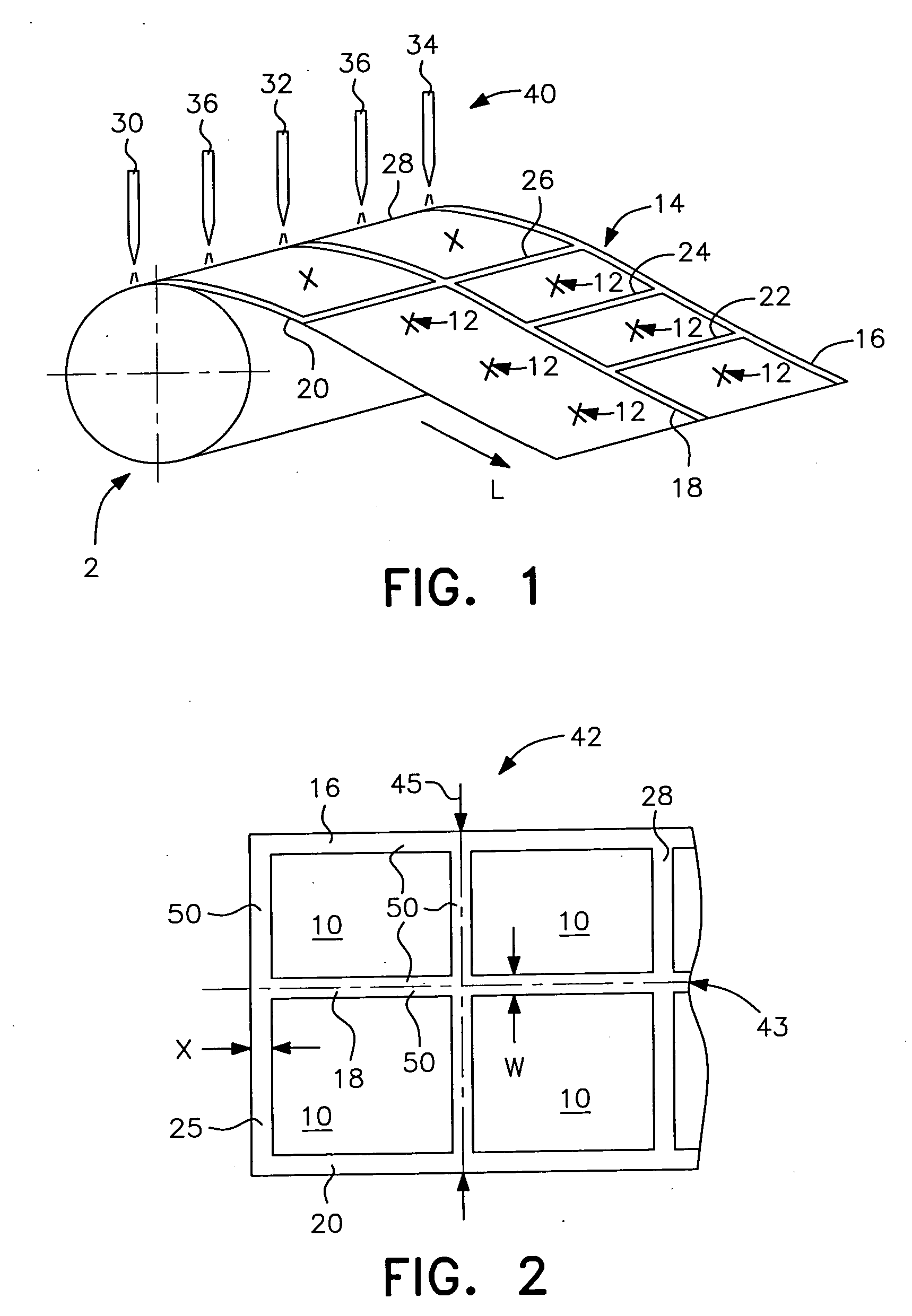
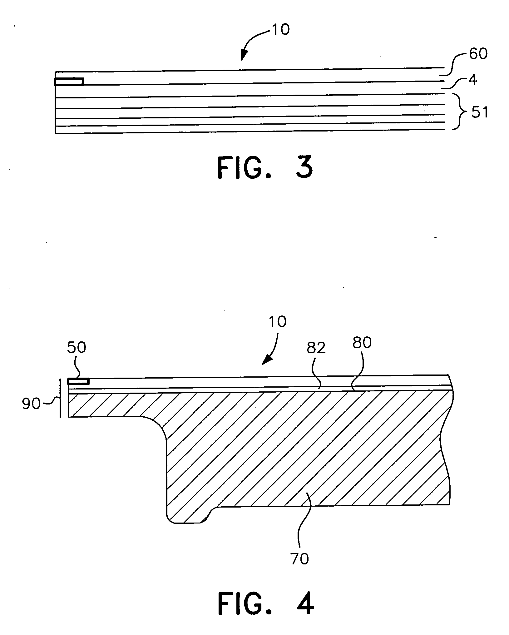
[0023]FIG. 1 is a perspective representative view of the invention to be described herein. In particular a roll 2 of substrate 4 is unwound and subjected to a printing process to be described herein. The substrate may be any variety of materials to be used as a floor covering such as paper, plastic or the like. In particular a floor covering 10 is produced by printing a decorative pattern 12, which includes a plurality of grid lines 14. More specifically the pattern of grid lines comprises a rectangular or square pattern including longitudinal lines 16, 18 and 20 and transverse lines 22, 24, 26 and 28. Such decorative patterns 12 and grid lines 14 can be applied by a v...


PUM

PropertyMeasurementUnit
sizeaaaaaaaaaa
perimeteraaaaaaaaaa
pressureaaaaaaaaaa

Abstract

A floor panel for an elevated floor including a printed border along the edge of the floor panel and a protective wear surface over the printed surface.

Description

[0001]This application is a continuation of application Ser. No. 10 / 211,643 filed Aug. 5, 2002.FIELD OF INVENTION[0002]This invention relates generally to a method of producing a floor panel for an elevated floor, including printing a border along the edge thereof, and includes the floor panel with the printed edge.BACKGROUND ART[0003]Elevated floors have been gaining widespread usage and prominence in view of the wide proliferation of computers installed and used in buildings. These elevated floors are sometimes called “computer floors”. Generally speaking such elevated floors are designed to be supported on pedestals at the corners of the elevated floor so as to present an access space between the elevated floor and the floor structure that can be used to run electrical cabling, computer lines, air conditioning or other heating systems.[0004]These computer floors comprise floor panels and are often provided with some form of floor covering laminated to the upper surface thereof to...

Claims


Application Information

Patent Timeline
Patent Type & Authority Applications(United States)
IPC IPC(8): E04F15/024B32B5/00B32B29/06B44C5/04
CPCB32B29/06B44C5/0446E04F15/02405Y10T156/1059Y10T428/24777Y10T156/1052Y10T156/1062Y10T156/1077
Inventor MEAD, BRUCE
Owner KINGSPAN HLDG (IRL) LTD
Why Eureka
Try Eureka