Portable air compressor/generator control method and system

a technology of air compressor and generator, which is applied in the field of welding systems, can solve the problems of increasing maintenance and repair costs

Active Publication Date: 2008-10-30
ILLINOIS TOOL WORKS INC
View PDF9 Cites 25 Cited by
  • Summary
  • Abstract
  • Description
  • Claims
  • Application Information

AI Technical Summary

Benefits of technology

[0004]In one embodiment, a welding generator is provided. The welding generator includes an engine, a compressor coupled to the engine, and a regulator coupled to the compressor and located on a control panel.

Problems solved by technology

In addition, the independence of the two units may result in an increased amount of maintenance and repair costs due to duplication of parts.

Method used


Image

  • Portable air compressor/generator control method and system
  • Portable air compressor/generator control method and system
  • Portable air compressor/generator control method and system

Examples


Embodiment Construction

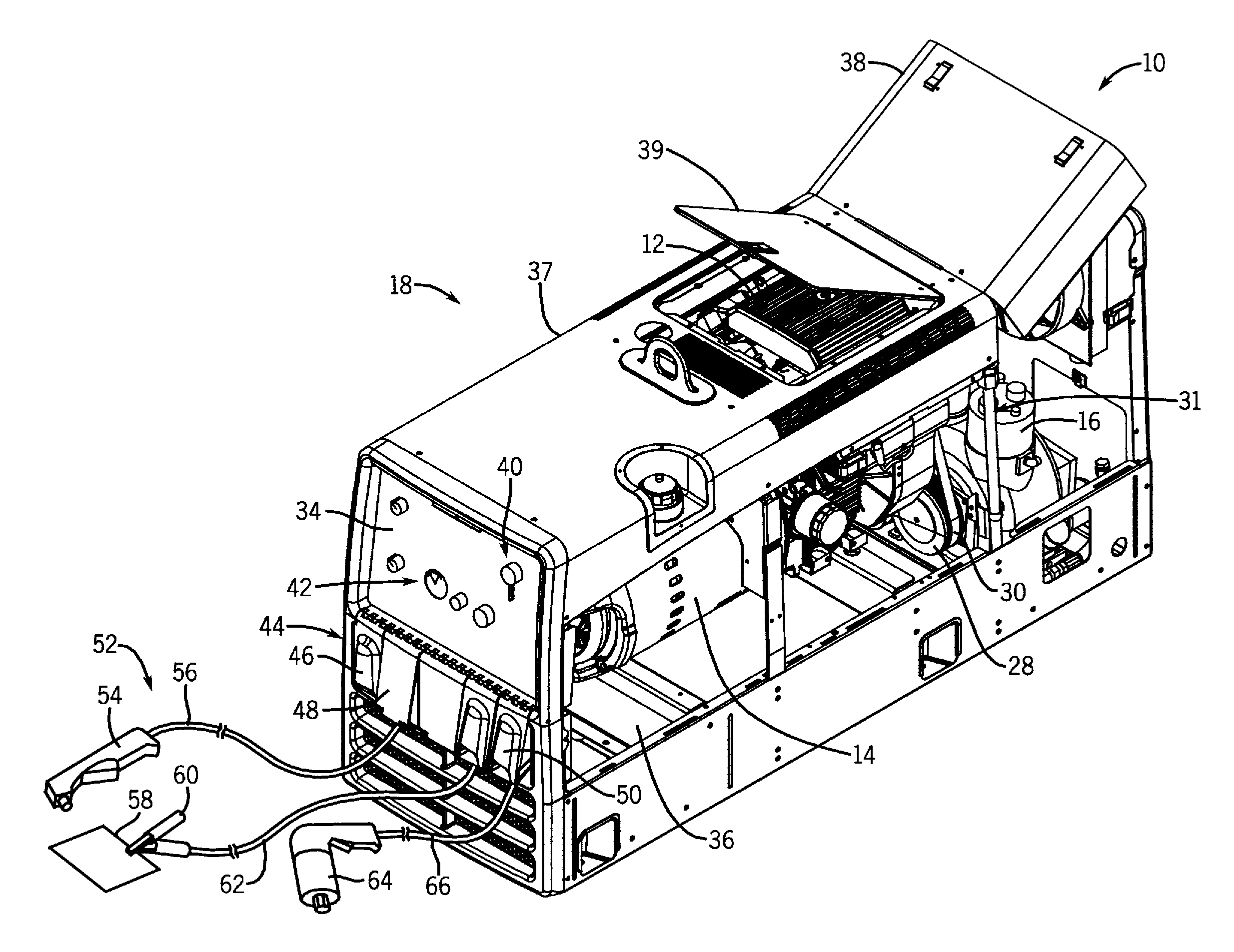
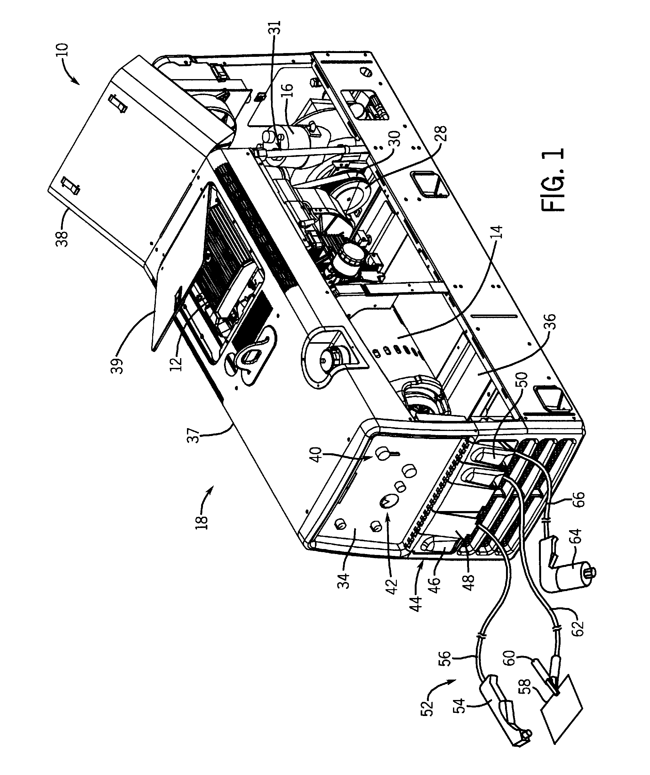
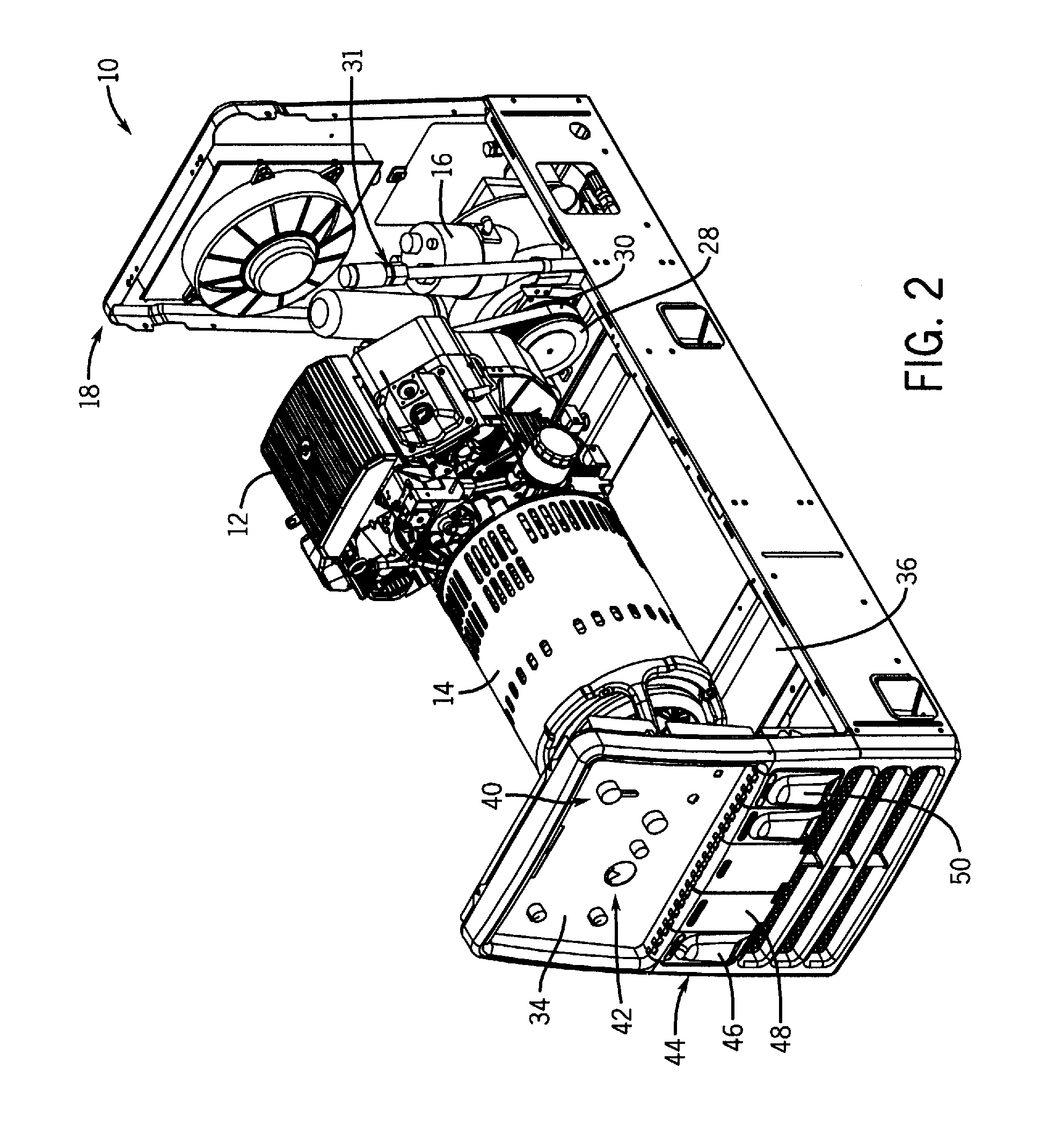
[0015]Referring now to the drawings, FIGS. 1-3 illustrate an engine-driven welding generator / compressor system 10 having an engine 12 drivingly coupled to a welding generator 14 and an air compressor 16 in a single enclosure 18 in accordance with an exemplary embodiment of the present technique. FIG. 1 is a partial perspective view of the system 10 with side access panels removed and top access panels or hatches rotated to open positions. FIG. 2 is another partial perspective view of the system 10 as illustrated in FIG. 1, wherein the entire top access panel assembly is removed to provide a better view of the internal features of the system 10. FIG. 3 is a side view of the system 10 as illustrated in FIGS. 1 and 2. As depicted, the system 10 is configured to provide multiple outputs, including welding current, alternating current (AC) power, and compressed air.

[0016]As discussed in detail below, the illustrated system includes a variety of features to improve serviceability, reliabi...


PUM

PropertyMeasurementUnit
critical pressureaaaaaaaaaa
pressureaaaaaaaaaa
timeaaaaaaaaaa

Abstract

A welding system is provided that includes an engine, a compressor coupled to the engine, and a regulator coupled to the compressor and located on a control panel. Another welding system is provided that includes an engine, a compressor coupled to the engine and a monitor circuit configured to monitor the duration of operation of the compressor by monitoring engagement of the clutch. A pressure gauge configured to be coupled to a compressor is also provided.

Description

BACKGROUND[0001]The invention relates generally to welding systems and more particularly to welding systems utilizing an engine coupled to an air compressor and welding generator in a single unit.[0002]Welding systems generally use an electrical current (e.g., welding current) to perform welding. The electrical current may be provided by an electrical power source (such as a power grid or battery) or an electrical generator coupled to a mechanical power source. Examples of mechanical power sources include engines that output power via a rotating drive shaft. Typically, the drive shaft is coupled to other devices that consume the energy provided by the rotating drive. For instance, welding systems often include internal combustion engines (such as gas or diesel engines) and an alternator or generator configured to convert the mechanical energy generated by the engine into electrical energy (e.g., electrical current). These systems are often referred to as engine-driven welding genera...

Claims


Application Information

Patent Timeline
Patent Type & Authority Applications(United States)
IPC IPC(8): B23K9/095
CPCF04C18/16F04C28/06F04C28/28B23K9/1006
Inventor LEISNER, JOHN C.KROPP, ERIC M.
Owner ILLINOIS TOOL WORKS INC
Why Eureka
Try Eureka