Fixed-focus lens system
a fixed-focus lens and lens system technology, applied in the field of lenses, can solve the problems of increasing the resolution of the image sensor, difficult to achieve the balance between the image circle, the imaging ratio and the overall length of the fixed-focus lens system, production cost and the overall length, etc., to achieve effective focal length, reduce the overall length of the lens system, and high image quality
- Summary
- Abstract
- Description
- Claims
- Application Information
AI Technical Summary
Benefits of technology
Problems solved by technology
Method used
Image
Examples
numerical embodiment 1
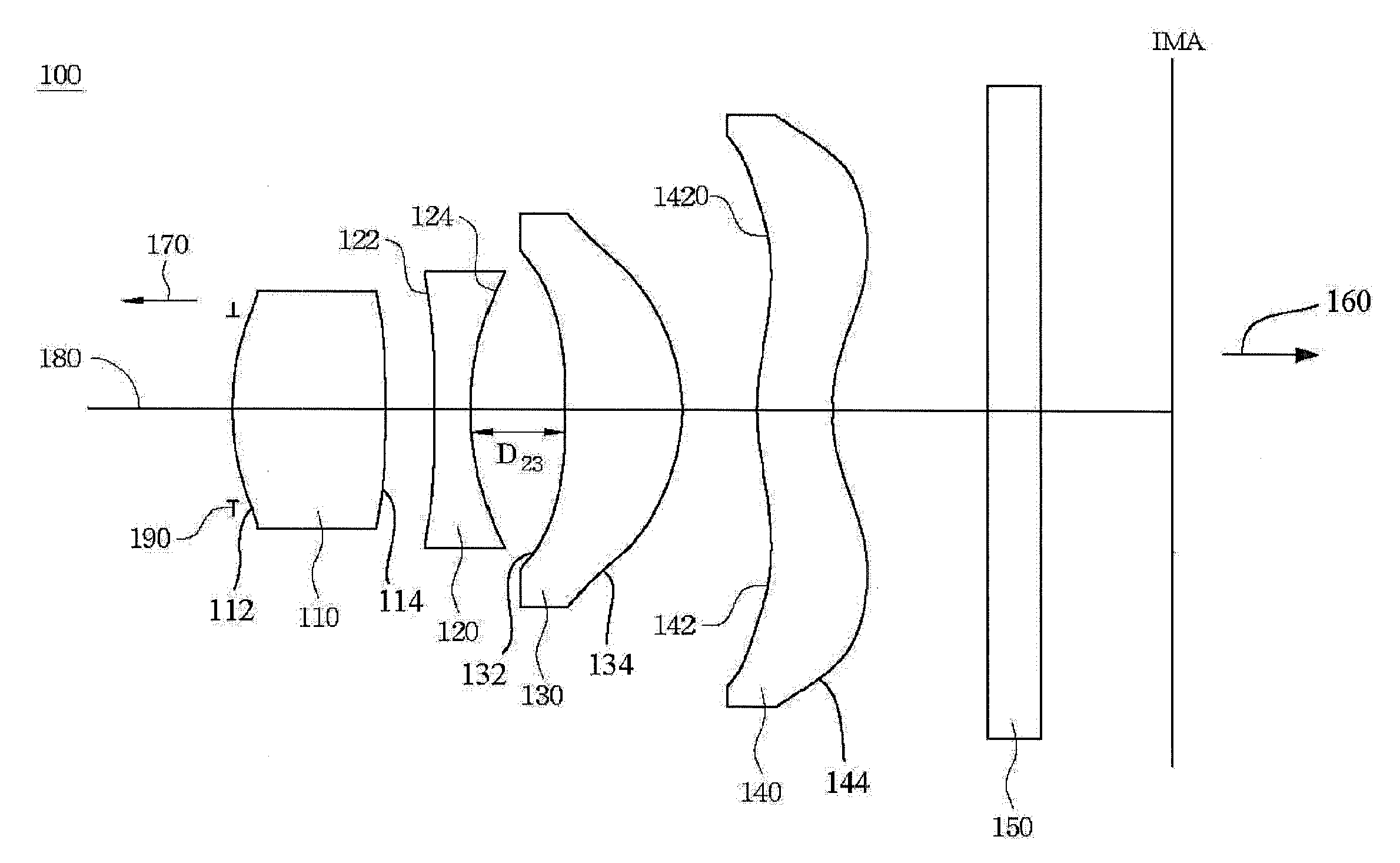
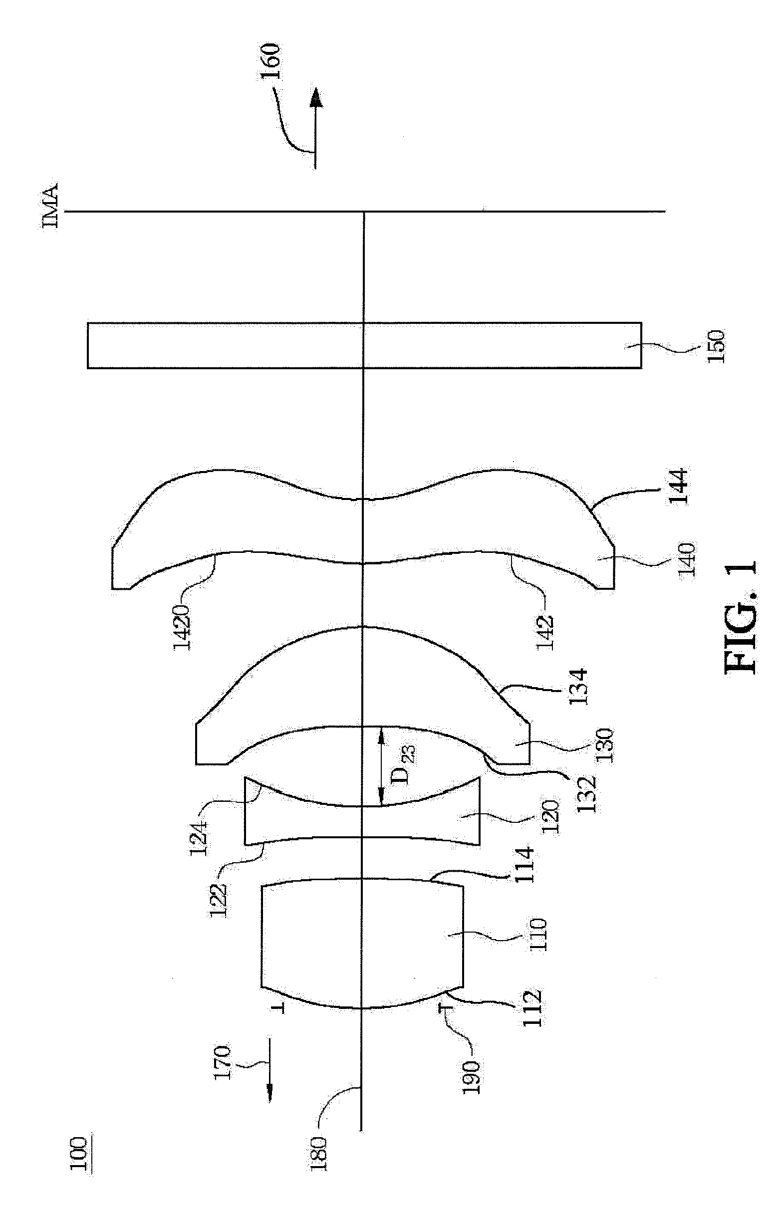
[0039]The optical parameters of the first positive lens 110, the second negative lens 120, the third positive meniscus lens 130 and the fourth negative lens 140 according to the Numerical Embodiment 1 are listed in Table 1 as provided below. In addition, in Table 1, “STO” represents the aperture stop 190, “FS” represents the optical filter 150 and “IMA” represents the image plane. In Numerical Embodiment 1, the object-side surface 122 of the second negative lens 120 has a positive curvature.
TABLE 1AbbeRadiusThickness orRefractive IndexNumberSurfaceCurvature (mm)Distance (mm)(Nd)(Vd)STOInfinity0.0S1124.282.261.62060.3S114−12.30.25S1221346.80.531.58529.9S1243.6541.42S132−7.7331.7371.521956.2S134−3.0440.472S142−3.6981.121.521956.2S1442.2972.28FSInfinity0.81.513964.1IMAInfinity
[0040]Other optical characteristics of Numerical Embodiment 1 of the fixed-focus lens system 100 are further listed in Table 2.
TABLE 2Effective Focal Length8.32 mmFiled of View59.4°F number3.0Image Circle 9.5 mmMa...
numerical embodiment 2
[0046]The optical parameters of the first positive lens 110, the second negative lens 120, the third positive meniscus lens 130 and the fourth negative lens 140 according to the Numerical Embodiment 2 are listed in Table 5 as provided below. In addition, in Table 5, “STO” represents the aperture stop 190, “FS” represents the optical filter 150 and “IMA” represents the image plane. In Numerical Embodiment 2, the object-side surface 122 of the second negative lens 120 has a negative curvature.
TABLE 5AbbeRadiusThickness orRefractive IndexNumberSurfaceCurvature (mm)Distance (mm)(Nd)(Vd)STOInfinity0.0S1124.4592.41.62060.3S114−10.5340.25S122−76.090.521.58529.9S1243.7661.29S132−9.1571.9761.514957.2S134−3.1760.599S1423.6871.1571.521956.2S1442.2922.109FSInfinity0.81.513964.1IMAInfinity
[0047]Other optical characteristics of Numerical Embodiment 2 of the fixed-focus lens system 100 are further listed in Table 6.
TABLE 6Effective Focal Length8.27 mmFiled of View58.1°F number3.0Image Circle 9.2 m...
numerical embodiment 3
[0052]The optical parameters of the first positive lens 110, the second negative lens 120, the third positive meniscus lens 130 and the fourth negative lens 140 according to the Numerical Embodiment 3 are listed in Table 9 as provided below. In addition, in Table 9, “STO” represents the aperture stop 190, “FS” represents the optical filter 150 and “IMA” represents the image plane. In Numerical Embodiment 3, the object-side surface 122 of the second negative lens 120 has a negative curvature much smaller than that for Numerical Embodiment 2.
TABLE 9AbbeRadiusThickness orRefractive IndexNumberSurfaceCurvature (mm)Distance (mm)(Nd)(Vd)STOInfinity0.0S1124.3532.41.62060.3S114−13.0640.25S122−2009.80.521.58529.9S1243.7791.4S132−8.2271.7351.514657.2S134−3.1150.404S1423.41.1151.521956.2S1442.2122.29FSInfinity0.81.513964.1IMAInfinity
[0053]Other optical characteristics of Numerical Embodiment 3 of the fixed-focus lens system 100 are further listed in Table 10.
TABLE 10Effective Focal Length8.27 ...
PUM
 Abstract
Description
Claims
Application Information
 - R&D
- Intellectual Property
- Life Sciences
- Materials
- Tech Scout
- Unparalleled Data Quality
- Higher Quality Content
- 60% Fewer Hallucinations
Browse by: Latest US Patents, China's latest patents, Technical Efficacy Thesaurus, Application Domain, Technology Topic, Popular Technical Reports.
© 2025 PatSnap. All rights reserved.Legal|Privacy policy|Modern Slavery Act Transparency Statement|Sitemap|About US| Contact US: help@patsnap.com


