Photovoltaic Roofing Wiring Array, Photovoltaic Roofing Wiring System and Roofs Using Them

Inactive Publication Date: 2008-11-06
CERTAINTEED CORP
View PDF31 Cites 73 Cited by
  • Summary
  • Abstract
  • Description
  • Claims
  • Application Information

AI Technical Summary

Benefits of technology

[0028]The present invention results in a number of advantages over the prior art. For example, the photovoltaic roofing wiring systems of the present invention can be installed by an installer who is relatively unskilled in the field of electrical interconnection. Moreover, the photovoltaic roofing wiring systems of the present invention can be constructed from individual modular parts, allowing the skilled artisan flexibil

Problems solved by technology

First, fossil fuels have become more and more expensive due to increasing scarcity and unrest in areas rich in petroleum deposits.
Second, there exists overwhelming concern about the effects of the combustion of fossil fuels on the environment, due to factors such as air pollution (from NOx, hydrocarbons and ozone) and global warming (from CO2).
Photovoltaic roofing elements are generally difficult to install, as they must not only be physically conne

Method used


Image

  • Photovoltaic Roofing Wiring Array, Photovoltaic Roofing Wiring System and Roofs Using Them
  • Photovoltaic Roofing Wiring Array, Photovoltaic Roofing Wiring System and Roofs Using Them
  • Photovoltaic Roofing Wiring Array, Photovoltaic Roofing Wiring System and Roofs Using Them

Examples


Embodiment Construction

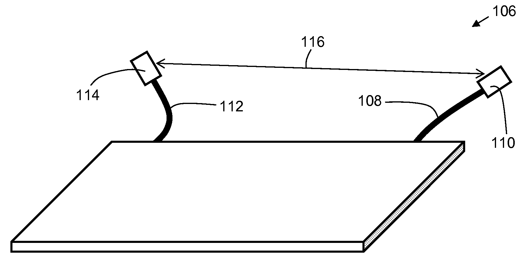
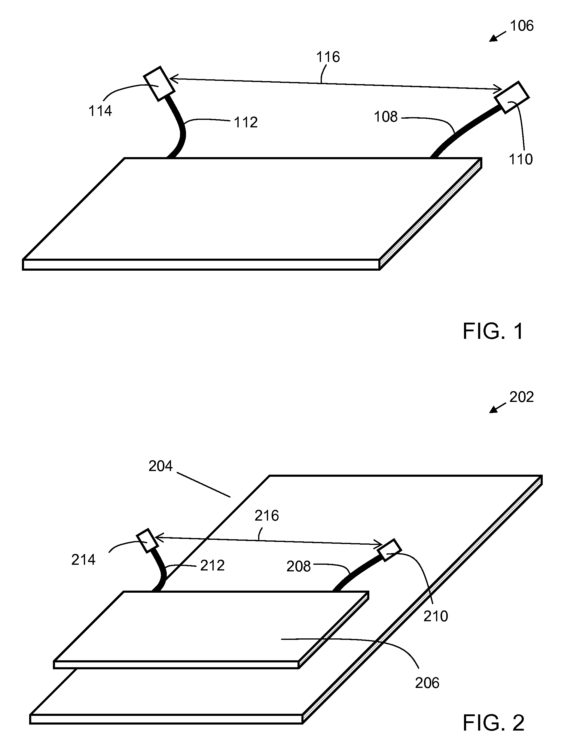
[0043]One aspect of the invention comprises a photovoltaic roofing wiring array configured for use with a photovoltaic element, an example of which is shown in top perspective view in FIG. 1. Photovoltaic element 106 includes a positive lead 108 terminated in a positive connector 110, and a negative lead 112 terminated in a negative connector 114. As shown in FIG. 1, the positive and negative leads may extend from the photovoltaic element. Alternatively, as the skilled artisan would appreciate, they can be integrally formed with the rest of the photovoltaic element, with the connectors mounted directly on the surface of the element. The lead-to-lead distance 116 is the distance spanning the connectorized ends of the leads of a single photovoltaic element. If one or both leads are flexible, the lead-to-lead distance is a range of distances, with a lower limit being the distance between the connectorized ends when they are brought together in closest proximity and an upper limit being...


PUM


Abstract

The present invention provides photovoltaic wiring arrays and photovoltaic wiring systems suitable for use in rooftop photovoltaic power generation systems. Accordingly, one aspect of the invention provides a photovoltaic roofing wiring array for use with a plurality of photovoltaic roofing elements, each photovoltaic roofing element having a positive lead terminated in a positive connector and a negative lead terminated in a negative connector, and a lead-to-lead distance between the positive connector and the negative connector, the photovoltaic roofing wiring system comprising: a positive parallel wiring run, the positive parallel wiring run comprising a main line and one or more connection branches pendant from the main line, each connection branch being terminated in a positive connector; and a negative parallel wiring run, the negative parallel wiring run comprising a main line and one or more connection branches pendant from the main line, each connection branch being terminated in a negative connector, wherein each positive connector is coupleable to the positive connectors of the photovoltaic roofing elements; and wherein each negative connector is coupleable to the negative connectors of the photovoltaic roofing elements. In some embodiments of the invention, the photovoltaic roofing wiring arrays are substantially prefabricated.

Description

BACKGROUND OF THE INVENTION[0001]1. Field of the Invention[0002]The present invention relates generally to photovoltaic roofing systems. The present invention relates more particularly to photovoltaic roof arrays and wiring systems for use therewith.[0003]2. Technical Background[0004]The search for alternative sources of energy has been motivated by at least two factors. First, fossil fuels have become more and more expensive due to increasing scarcity and unrest in areas rich in petroleum deposits. Second, there exists overwhelming concern about the effects of the combustion of fossil fuels on the environment, due to factors such as air pollution (from NOx, hydrocarbons and ozone) and global warming (from CO2). In recent years, research and development attention has focused on harvesting energy from natural environmental sources such as wind, flowing water and the sun. Of the three, the sun appears to be the most widely useful energy source across the continental United States; mos...

Claims


Application Information

Patent Timeline
IPC IPC(8): H01L31/042
CPCH01L31/02008H01L31/05Y02B10/12Y02E10/50H02S20/23H01L31/0504Y02B10/20H02S40/36F24J2/5245Y02B10/10
Inventor KALKANOGLU, HUSNU M.JACOBS, GREGORY F.SHAW, WAYNE E.
Owner CERTAINTEED CORP
Why Eureka
Try Eureka