Flat-hose assembly for wound drainage system

a technology of wound drainage and hoses, which is applied in the direction of flexible pipes, intravenous devices, other medical devices, etc., can solve the problems of creating pressure points on patients, wounds or other patient discomfort, and difficulty in making an airtight seal between the dressing and the tubing

Active Publication Date: 2008-11-06
CONVATEC LTD
View PDF99 Cites 102 Cited by
  • Summary
  • Abstract
  • Description
  • Claims
  • Application Information

AI Technical Summary

Problems solved by technology

Several disadvantages exist with the existing systems.
First, it is difficult to make an airtight seal between the dressing and the tubing.
Second, the round tubing at the wound site often creates pressure points on the patient as the patient moves around.
The round tubing may end up underneath the patient, causing wounds or other patient discomfort.
A third disadvantage to the currently available systems is that it is easy to cause the tubing to be bent or kinked, blocking the flow of exudates and inhibiting the application of negative pressure.

Method used


Image

  • Flat-hose assembly for wound drainage system
  • Flat-hose assembly for wound drainage system
  • Flat-hose assembly for wound drainage system

Examples


Embodiment Construction

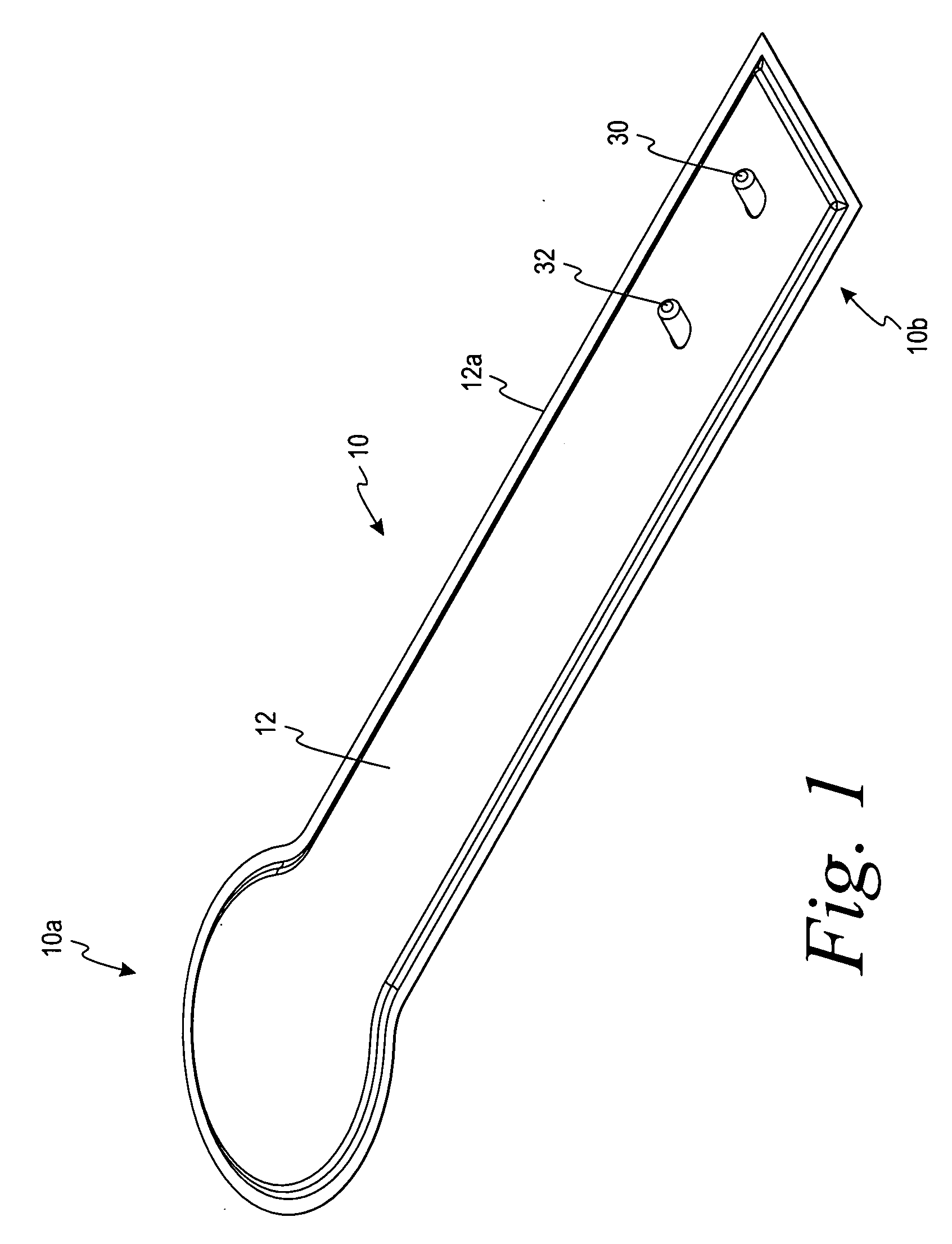
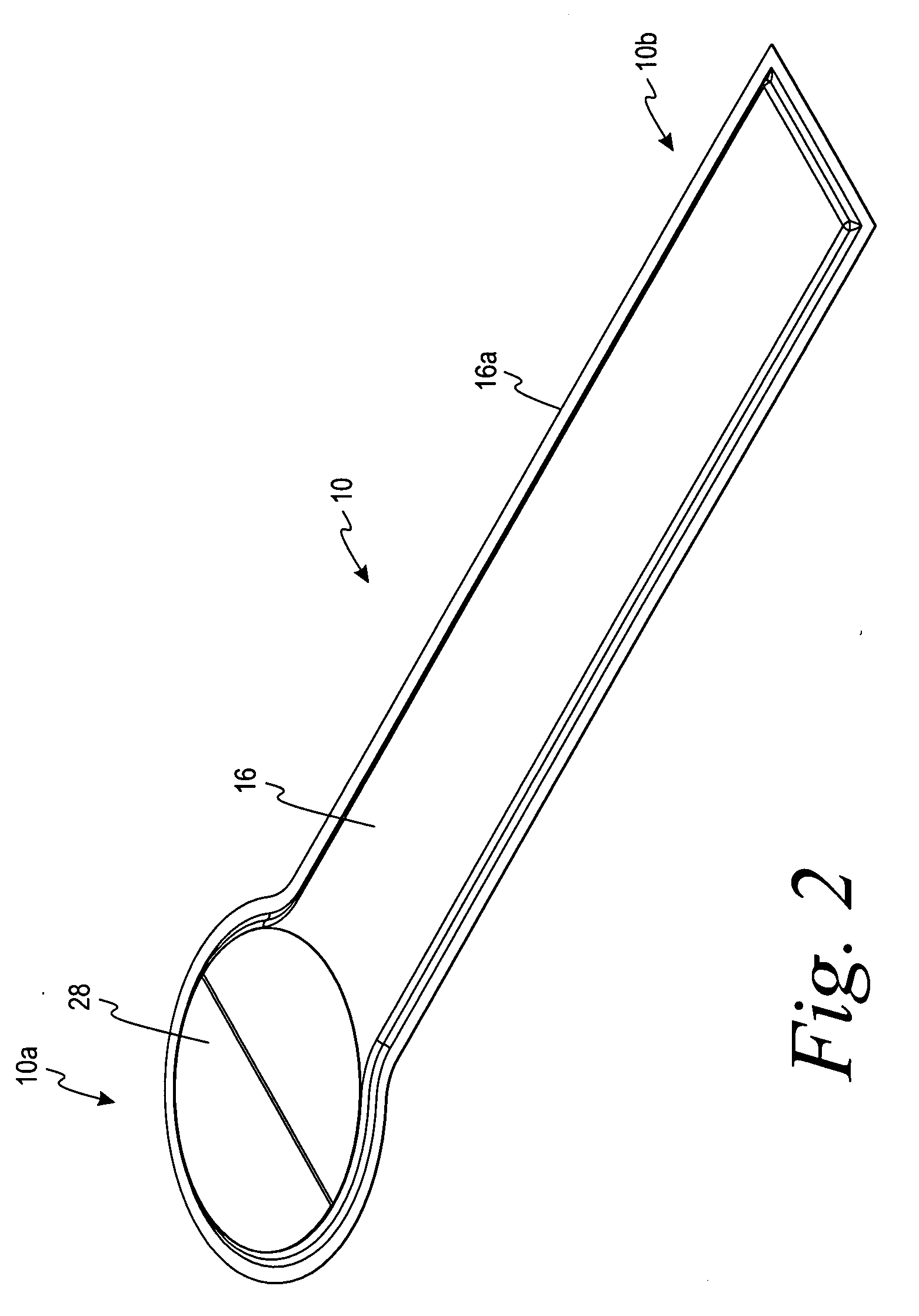
[0015]As shown in FIGS. 1-4, a flat-hose assembly 10 for use in a wound drainage system is shown. The flat-hose assembly 10 has a top layer 12, a filter layer 14, and a bottom layer 16. The filter layer 14 is located between the top layer 12 and the bottom layer 16. The top layer 12 and the bottom layer 16 form a seal along a periphery 12a of the top layer 12 and a periphery 16a of the bottom layer 16 such that the filter layer 14 is disposed between the top layer 12 and the bottom layer 16. The filter layer 14 is enclosed within the top layer 12 and the bottom layer 16.

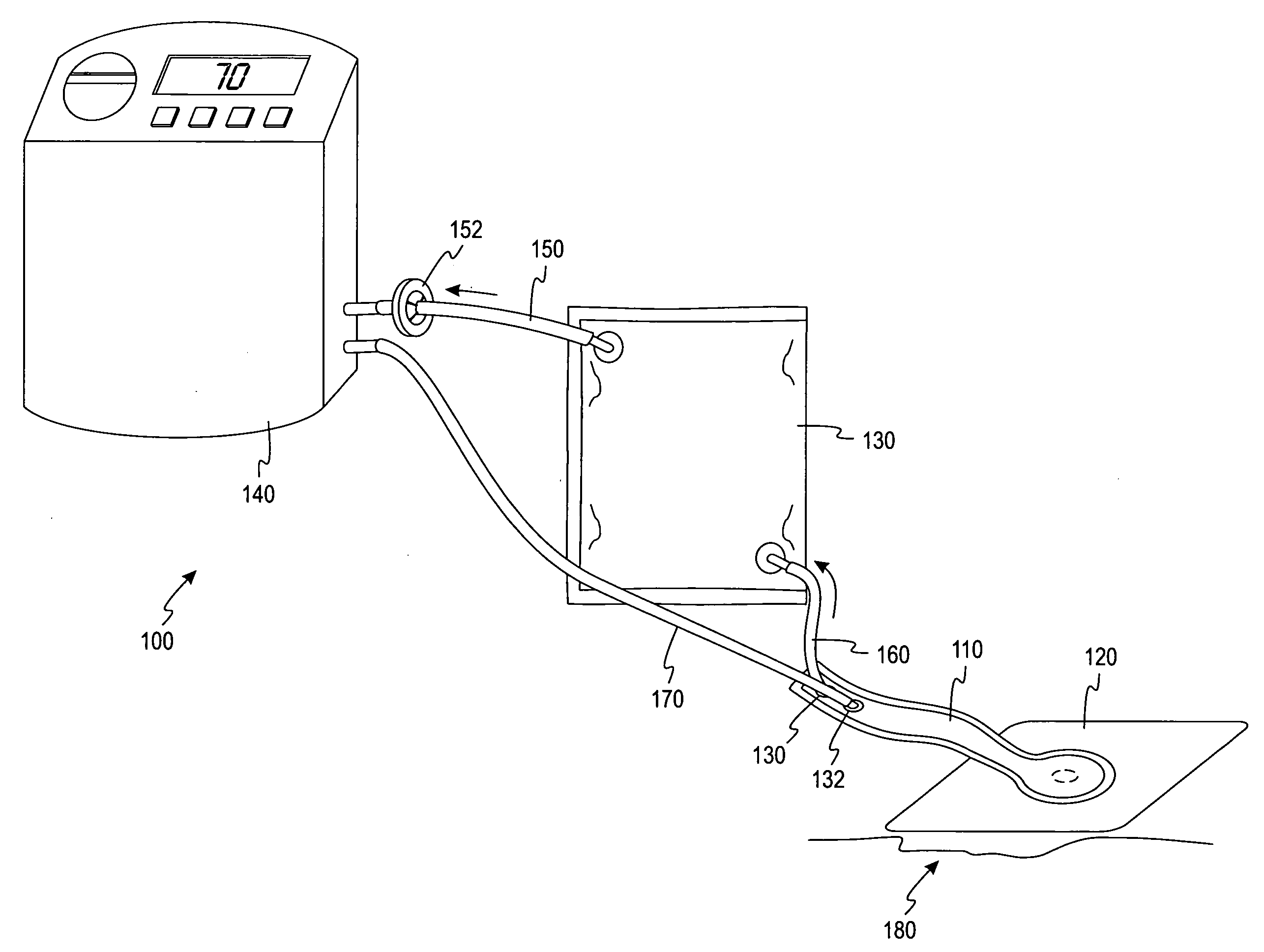
[0016]The flat-hose assembly 10 has a distal end 10a and a proximal end 10b. The distal end 10a is generally larger than the proximal end 10b of the flat-hose assembly 10. The distal end 10a is adapted to interact with a wound dressing to allow exudates from a wound to flow into the wound drainage system (see FIG. 5). The distal end 10a The proximal end 10b is adapted to allow exudates to flow away from the wound and...


PUM


Abstract

A flat-hose assembly has a proximal end and a distal end adapted for use with a negative pressure wound drainage system. The flat-hose assembly comprises a top layer, a bottom layer, and a filter layer. The bottom layer forms an opening at the distal end of the flat-hose assembly to allow exudates of a wound to flow into the flat-hose assembly. The filter layer is disposed between the top layer and the bottom layer. The top and bottom layer form a seal area along a periphery of the top layer and the bottom layer to seal the filter layer therebetween.

Description

FIELD OF INVENTION[0001]The invention relates to systems for treating wounds by the application of negative pressure and to devices for use in such systems.BACKGROUND OF THE INVENTION[0002]Negative pressure, also referred to as suction, has proven to be a successful technique for the healing of wounds. Negative pressure is applied by a vacuum source through tubing that is attached to a dressing that covers a wound and healthy skin beyond the wound perimeter. Present systems typically use commercially available round tubing made of various materials such as, PVC, nylon, urethane, or similar polymeric materials. One end of the tubing is connected to the vacuum source and a collection device is located between the vacuum source and the wound. A second end of the tubing passes through the dressing in order to evacuate exudates from the wound and place the exudates into the collection device. An airtight seal needs to be maintained between the healthy skin and the dressing as well as bet...

Claims


Application Information

Patent Timeline
Patent Type & Authority Applications(United States)
IPC IPC(8): F16L11/00
CPCA61M1/0088A61M2205/3344F16L11/121A61M2205/7536A61M1/915A61M1/913A61M1/966A61M1/98
Inventor BIGGIE, LYDIA B.DAWSON, JOHN A.
Owner CONVATEC LTD
Why Eureka
Try Eureka