Flashng bottle pourer

a bottle pourer and flashing technology, applied in the field of fluid dispensing, can solve the problems of time-consuming and uncost-effective procedures

Inactive Publication Date: 2008-11-06
BUKER CHRISTOPHER W +1
View PDF5 Cites 46 Cited by
  • Summary
  • Abstract
  • Description
  • Claims
  • Application Information

AI Technical Summary

Problems solved by technology

However, this procedure is time consuming and hence not cost effective.

Method used


Image

  • Flashng bottle pourer
  • Flashng bottle pourer
  • Flashng bottle pourer

Examples


Embodiment Construction

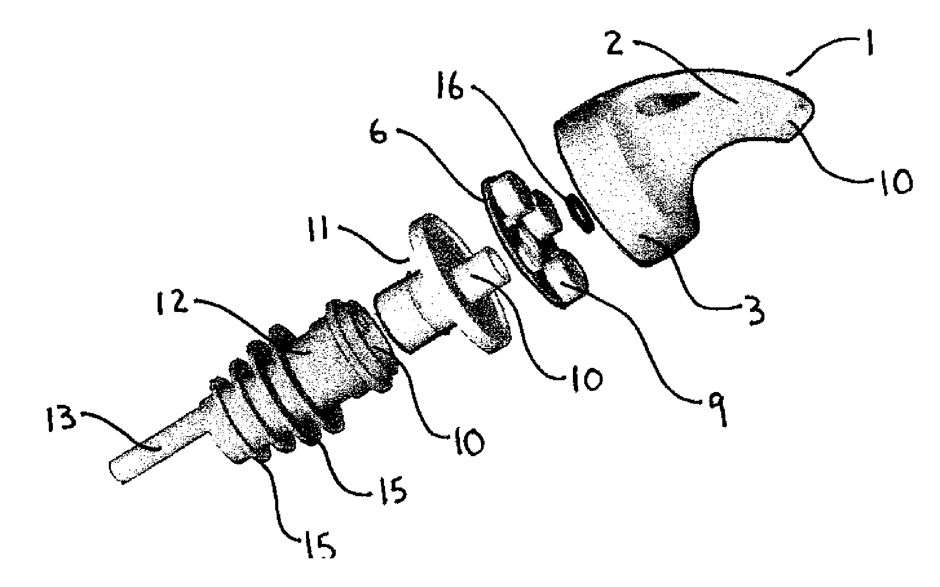
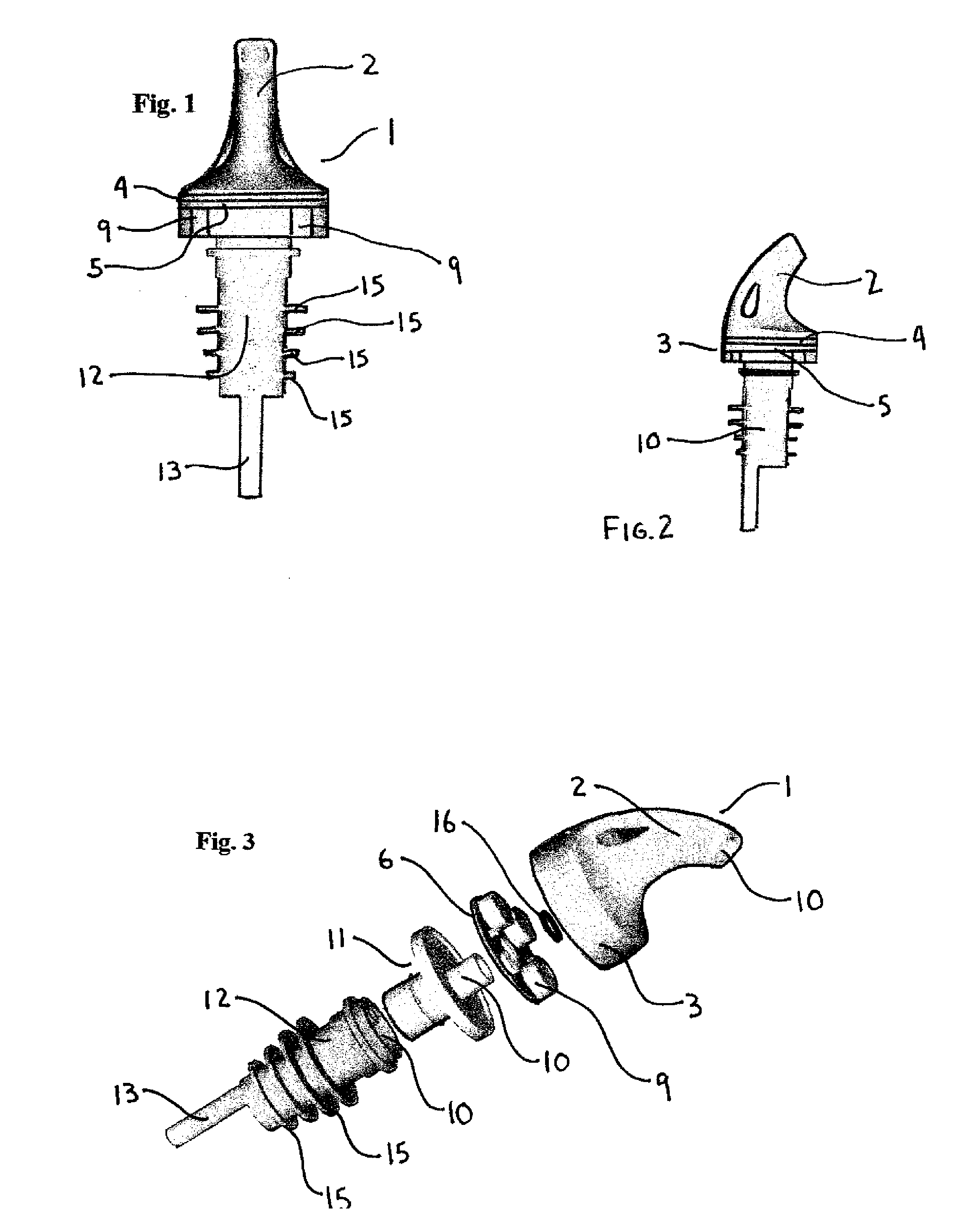
[0018]A bottle pourer, especially for liquor bottles, has an irregularly shaped top 1 and a stopper-sealing base 12. The top 1 has a pourer spout 2 generally as shown in FIGS. 2 and 3. At the lower part of the pourer top 1 is a cylindrical base 3. This cylindrical base 3 contains the electronics of the present invention. A central pouring corridor 10 runs longitudinally through the inner part of the cylindrical base. The electronic circuit board 5 is essentially doughnut shaped with a hole in the central part to accommodate the central pouring corridor.

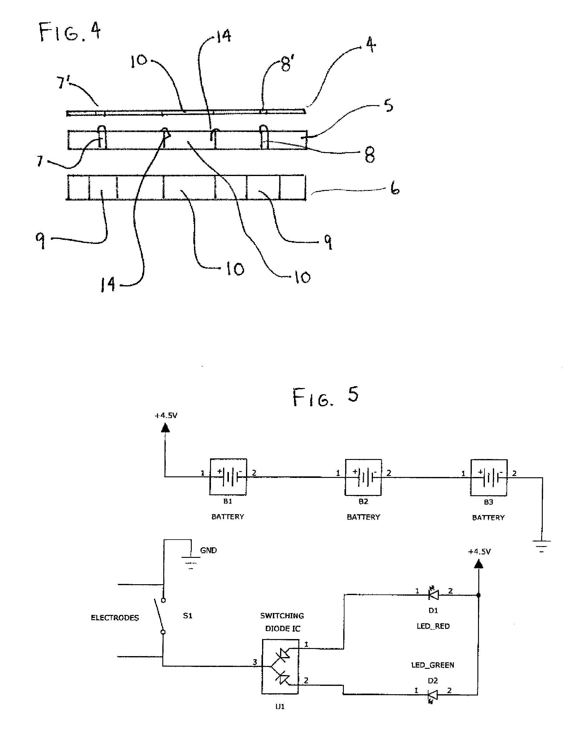
[0019]Sealed inside the base 3 are a top reflector ring 4, a circuit board 5, a battery base 6 and batteries 9. The electronic elements of this invention are best shown on FIGS. 3, 4 and 5. The top cylindrical reflector ring 4 is very thin, with a hole in the central part to accommodate the central pouring corridor 10, and has a reflective upper surface to highlight the visual effect of the left 7 and right 8 LEDs. The reflector ring ...


PUM


Abstract

A lighted bottle pourer has a standard shape and size top spout and lower stopper base. The bottle pourer is inserted into the top of a liquor bottle. Inside the top spout is a circuit board having two small liquid activated leads that stick out into the central pouring tube. The circuit board containing the electronics also has two LEDs that protrude through a reflective ring and a power supply of batteries. When liquid is poured from the bottle, through the spout and out of the top, the liquid activated leads cause the electrical circuit to be energized and light up the LEDs. When the bartender is finished pouring out the liquor, the leads return the electronic circuit to the open position and the LEDs are shut off.

Description

BACKGROUND OF THE INVENTION[0001]This invention relates to the field of fluid dispensing. More particularly, a lighted and flashing liquor bottle pourer is presented.[0002]The field of liquid dispensing has many tasks and devices have been introduced to solve many different problems. For example, fountain dispensers have evolved over the past decades from owner operated to customer dispensing units. Different inventions and improvements have been made to increase productivity or the enjoyment of beverages over the years.[0003]In the liquor bartending business in particular, various types of inventions have been devised to aid the bartender in his daily work. A bartender has to pour liquor from many different bottles over the course of a day's work. In addition, he or she has to pour discreet amounts of liquor or other drinks into glasses in order to create the various drinks served. A bartender may use a jigger, or measuring glass, to prepare drinks. However, this procedure is time ...

Claims


Application Information

Patent Timeline
Patent Type & Authority Applications(United States)
IPC IPC(8): B65D5/66
CPCB65D47/06B65D51/248B65D2547/063
Inventor BUKER, CHRISTOPHER W.LANDON, SCOTT
Owner BUKER CHRISTOPHER W
Why Eureka
Try Eureka