Stackable chair

a stacking chair and seat technology, applied in the field of stacking chairs, can solve the problems of unstable and over-compensated stacking chairs, and achieve the effect of preventing the stack from leaning forward and providing for the stability of the stacking chair

Inactive Publication Date: 2008-11-13
BARTLMAE KERSTIN
View PDF37 Cites 19 Cited by
  • Summary
  • Abstract
  • Description
  • Claims
  • Application Information

AI Technical Summary

Benefits of technology

[0006]A stacking chair having a seat, a back support, and a frame for supporting the seat and back support. The frame includes a pair of spaced apart leg members, a back support member, and a seat support member. Each of the pair of spaced apart leg members has a front leg portion and a rear leg portion, and a connection portion connecting the rear leg portion to the front leg portion. A seat support member extends between the pair of leg members and supports the seat. The connection portions of the leg members are connected to the seat support member. The stacking chair further includes a stacking member disposed on each of the pair of leg members. The stacking member is shaped to receive the connection portion of a like chair such that the stacking member rests on the connection portion of a like chair and the upper chair in a stack of chairs is positioned slightly forward of the lower chair a predetermined distance thereby offsetting the stacks tendency to lean back due to the weight and position of the back support while at the same time preventing the stack from leaning forward and thus providing for the stability of a stack of chairs.

Problems solved by technology

As the stacking chairs are placed atop each other, the weight and position of the back support of the chairs may cause the stack to lean towards the direction of the back supports (backwards) and thus collapse.
Attempts to correct the tendency of a stack to lean backwards has resulted in over-compensation and thus as a stack grows higher with each chair, the over-compensated stack of chairs tend to lean forward and become unstable.

Method used


Image

  • Stackable chair
  • Stackable chair
  • Stackable chair

Examples


Embodiment Construction

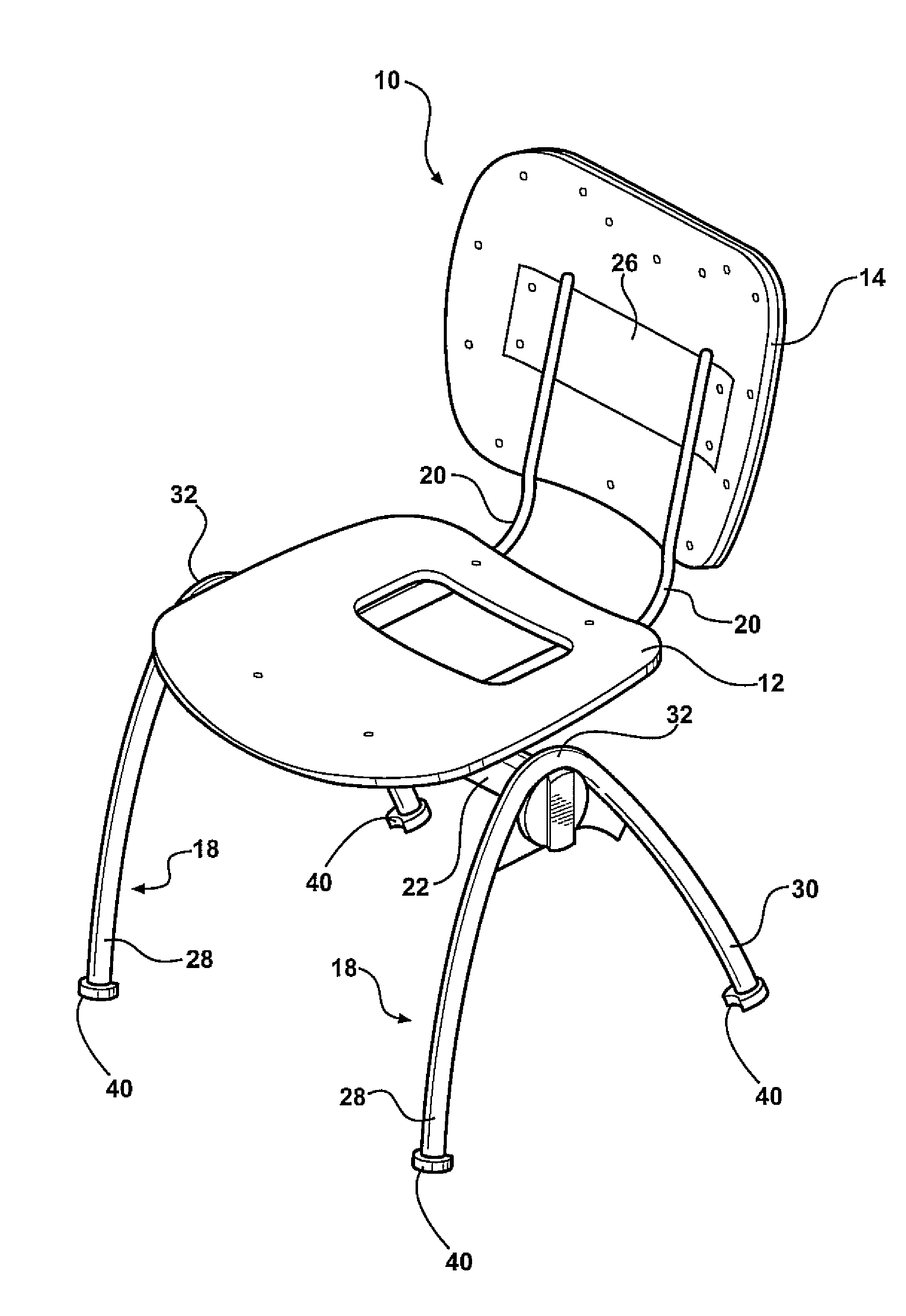
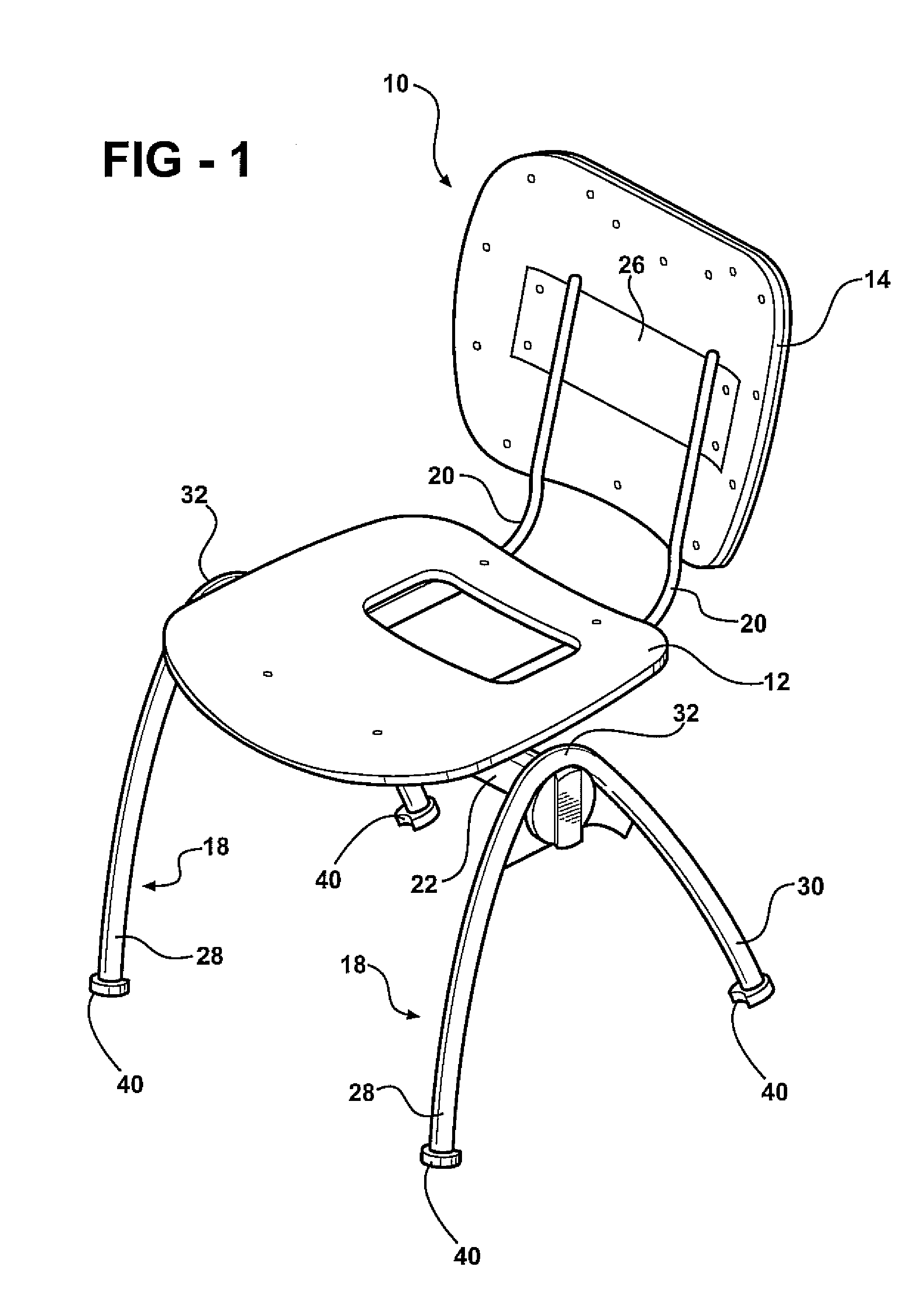
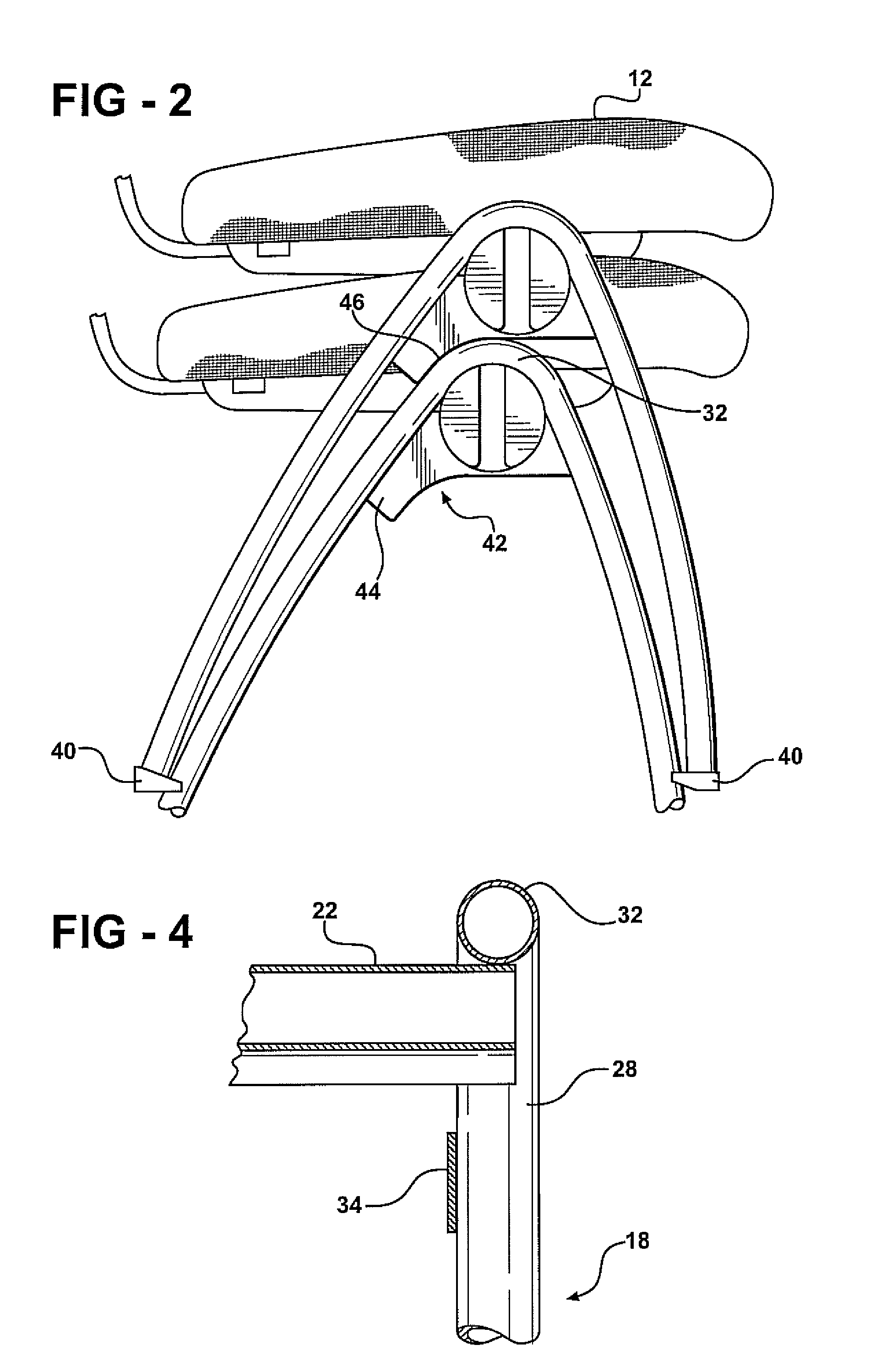
[0015]Referring to the Figures, wherein like numerals indicate corresponding parts throughout the several views, a stacking chair 10 is provided: FIG. 1 illustrates a stacking chair 10 according to an embodiment of the present invention. The stacking chair 10 is designed such that multiple chairs of the same likeness may be stacked one atop another for storage or transportation, as shown in FIG. 2. Additionally, the chair is equipped with features which allow for the chairs to be interconnected with similarly equipped chairs in a side-by-side relationship. The stacking chair 10 includes a seat 12, a back support 14, and a frame 16.

[0016]With reference now to FIGS. 3a and 3b, the frame 16 includes a pair of leg members 18, a back support member 20, and a seat support member 22. Each leg member 18 generally has the shape of an inverted U or inverted V and is symmetric to the other. The leg members 18 and are shaped such that the leg members 18 of an upper chair of the same likeness ma...


PUM


Abstract

A stacking chair having a seat, a back support, and a frame for supporting the seat and back support. The frame includes a pair of spaced apart leg members, a back support member, and a seat support member. The leg members have a front portion and rear portion interconnected by a connecting portion to give the leg members a generally U or V shape. The chair further includes a stacking member disposed on each leg member. The stacking member shaped to receive the upper surface of a leg member of a like chair such that the stacking member rests on the connection portion of a like chair and the upper chair in the stack is positioned forward of the lower chair thereby offsetting the stack's tendency to lean back due to the weight and position of the back support thus providing for the stability of a stack of chairs.

Description

CROSS REFERENCE TO RELATED APPLICATION[0001]This application claims the benefit of U.S. provisional patent application Ser. No. 60 / 916,982 filed May 9, 2007.BACKGROUND OF THE INVENTION[0002]1. Field of the Invention[0003]The present invention relates generally to a stacking chair having a stacking member that helps stabilize the stacking of like chairs atop one another.[0004]2. Description of the Prior Art[0005]A stacking chair typically includes a horizontal seat, a back support, and a frame for supporting the seat and back support. The frame typically includes a pair of spaced apart leg members, a seat support member for supporting the seat and a back support member for supporting the back support. As the stacking chairs are placed atop each other, the weight and position of the back support of the chairs may cause the stack to lean towards the direction of the back supports (backwards) and thus collapse. Attempts to correct the tendency of a stack to lean backwards has resulted i...

Claims


Application Information

Patent Timeline
Patent Type & Authority Applications(United States)
IPC IPC(8): A47C3/04
CPCA47C1/124A47C3/04
Inventor BARTLMAE, KERSTIN
Owner BARTLMAE KERSTIN
Why Eureka
Try Eureka