Self-aligned and extended inter-well isolation structure

a self-aligning and inter-well isolation technology, applied in the field of intra-well isolation structure, can solve problems such as additional processing steps

Inactive Publication Date: 2008-11-20
GLOBALFOUNDRIES INC
View PDF9 Cites 338 Cited by
  • Summary
  • Abstract
  • Description
  • Claims
  • Application Information

AI Technical Summary

Benefits of technology

[0030]Alternatively, at least one of the third depth and the fourth depth may be less than the first depth. In this case, the p-well abuts one of the pair of substantially vertical first trench sidewalls, the n-well abuts the other of the ...

Problems solved by technology

In addition, there exists a need for such an inter-well trench isolation structure that requ...

Method used


Image

  • Self-aligned and extended inter-well isolation structure
  • Self-aligned and extended inter-well isolation structure
  • Self-aligned and extended inter-well isolation structure

Examples


first embodiment

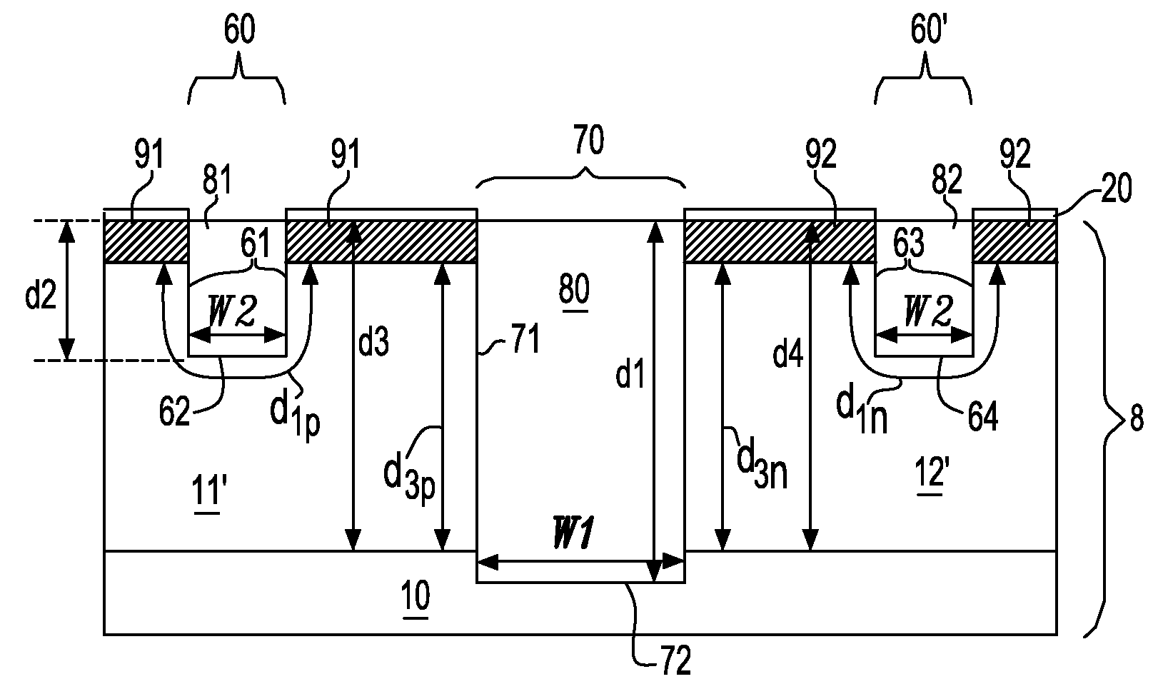
[0081]The first depth d1 is greater than the second depth d2 and the first width W1 is greater than the second width W2. In a variation of the first embodiment, the first intra-well isolation trench and the second intra-well isolation trench may have two different widths, which are less than the first width W1.

[0082]Both the third depth d3, which is the depth of the p-well 11, and the fourth depth d4, which is the depth of the n-well, are greater than the first depth d1. The p-well 11 and the n-well 12 abut the substantially horizontal first trench bottom surface 72.

[0083]Each of the vertical p-well to substrate layer interface 21 and the vertical n-well to substrate layer interface 22 is separated from one of the pair of substantially vertical first trench sidewalls 71 by a distance equal to the thickness of the extended pedestal layer 40. This is because the vertical p-well to substrate layer interface 21 coincides with the second pedestal sidewall 39′, the vertical n-well to subs...

third embodiment

[0108]The first depth d1 is greater than the second depth d2 and the first width W1 is greater than the second width W2. In a variation of the third embodiment, the first intra-well isolation trench and the second intra-well isolation trench may have two different widths, which are less than the first width W1.

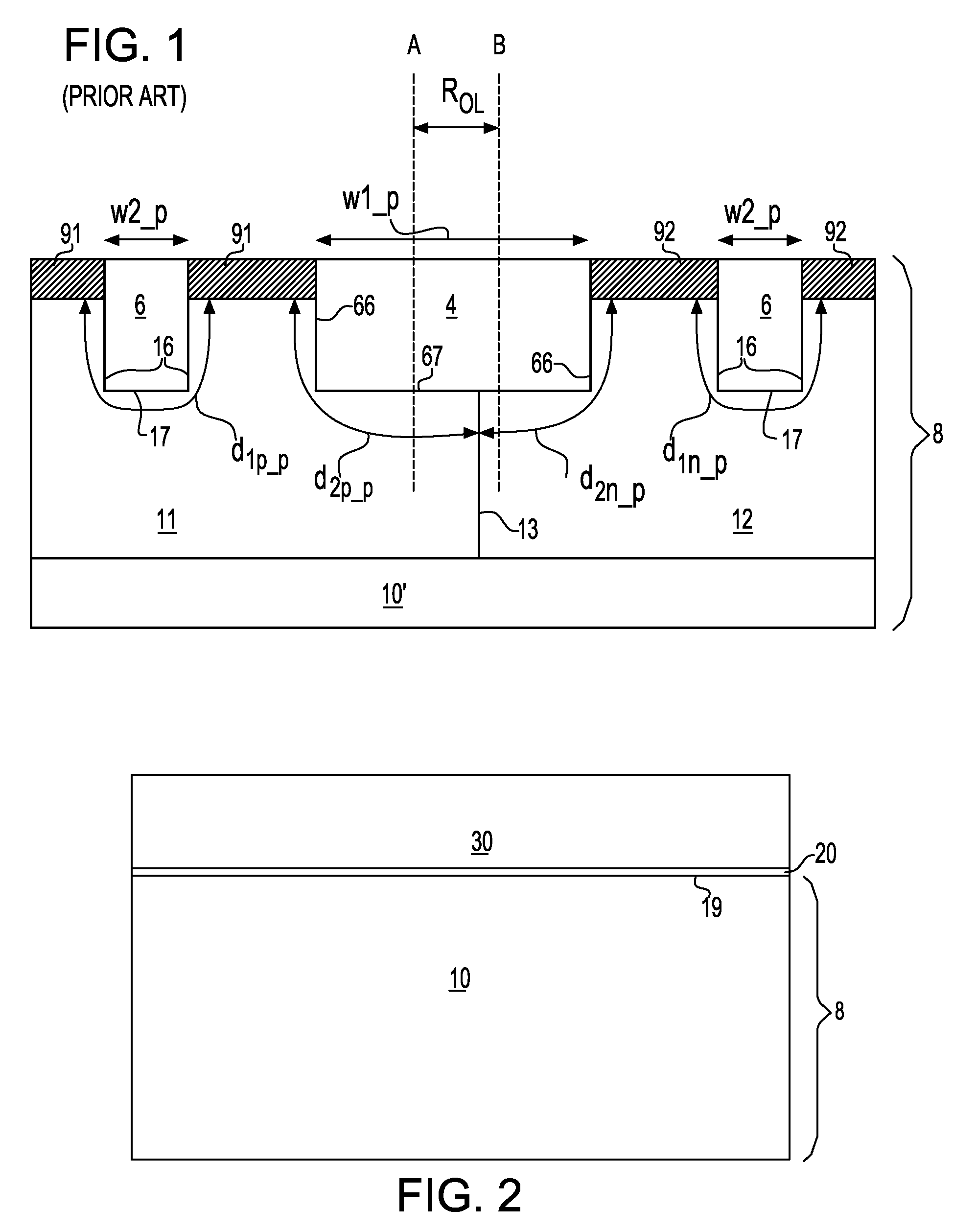
[0109]At least one of the third depth d3, which is the depth of the p-well 11, and the fourth depth d4, which is the depth of the n-well, is less than the first depth d1. In other words, only the third depth d3 may be less than the first depth d1, only the fourth depth d4 may be less than the fist depth d1, or both the third depth d3 and the fourth depth d4 may be less than the first depth d1. At least one of the p-well 11 and the n-well 12 do not abut the substantially horizontal first trench bottom surface 72. If the third depth d3 is less than the first depth d1, the p-well 11 does not abut the substantially horizontal first trench bottom surface 72. If the fourth depth d4 ...


PUM


Abstract

A pedestal is formed out of the pad layer such that two edges of the pedestal coincide with a border of the wells as implanted. An extended pedestal is formed over the pedestal by depositing a conformal dielectric layer. The area of the extended pedestal is exposed the semiconductor surface below is recessed to a recess depth. Other trenches including at least one intra-well isolation trench are lithographically patterned. After a reactive ion etch, both an inter-well isolation trench and at least one intra-well isolation trench are formed. The width of the inter-well isolation trench may be reduced due to the deeper bottom surface compared to the prior art structures. The boundary between the p-well and the n-well below the inter-well isolation structure is self-aligned to the middle of the inter-well isolation structure.

Description

FIELD OF THE INVENTION[0001]The present invention relates to a semiconductor structure, and particularly to an intra-well isolation structure having an extended depth relative to an inter-well isolation structure and self-aligned to a boundary between a p-well and an n-well, and methods of manufacturing the same.BACKGROUND OF THE INVENTION[0002]A typical semiconductor device in a complementary metal-oxide-semiconductor (CMOS) circuit is formed in a p-well or an n-well in a semiconductor substrate. Since other semiconductor devices are also present in the semiconductor substrate, the semiconductor device requires electrical isolation from adjacent semiconductor devices. Electrical isolation is typically provided by isolation structures that employ trenches filled with an insulator material. Electrical isolation of the semiconductor device from other devices located in the same well is called “intra-well isolation.” Electrical isolation of the semiconductor device from other devices i...

Claims


Application Information

Patent Timeline
IPC IPC(8): H01L29/00H01L21/762
CPCH01L21/3086H01L21/76229H01L21/823878
Inventor DYER, THOMAS W.LUO, ZHIJIONGYANG, HAINING S.
Owner GLOBALFOUNDRIES INC
Why Eureka
Try Eureka