
Control method for a variable displacement refrigerant compressor in a high-efficiency AC system

a technology of variable displacement and compressor, which is applied in refrigeration components, transportation and packaging, light and heating equipment, etc., can solve the problems of high overall system cost, and achieve the effects of preventing compressor operation, and reducing the number of compressors

Inactive Publication Date: 2008-11-27
DELPHI TECH INC
View PDF6 Cites 43 Cited by
  • Summary
  • Abstract
  • Description
  • Claims
  • Application Information

AI Technical Summary

Benefits of technology

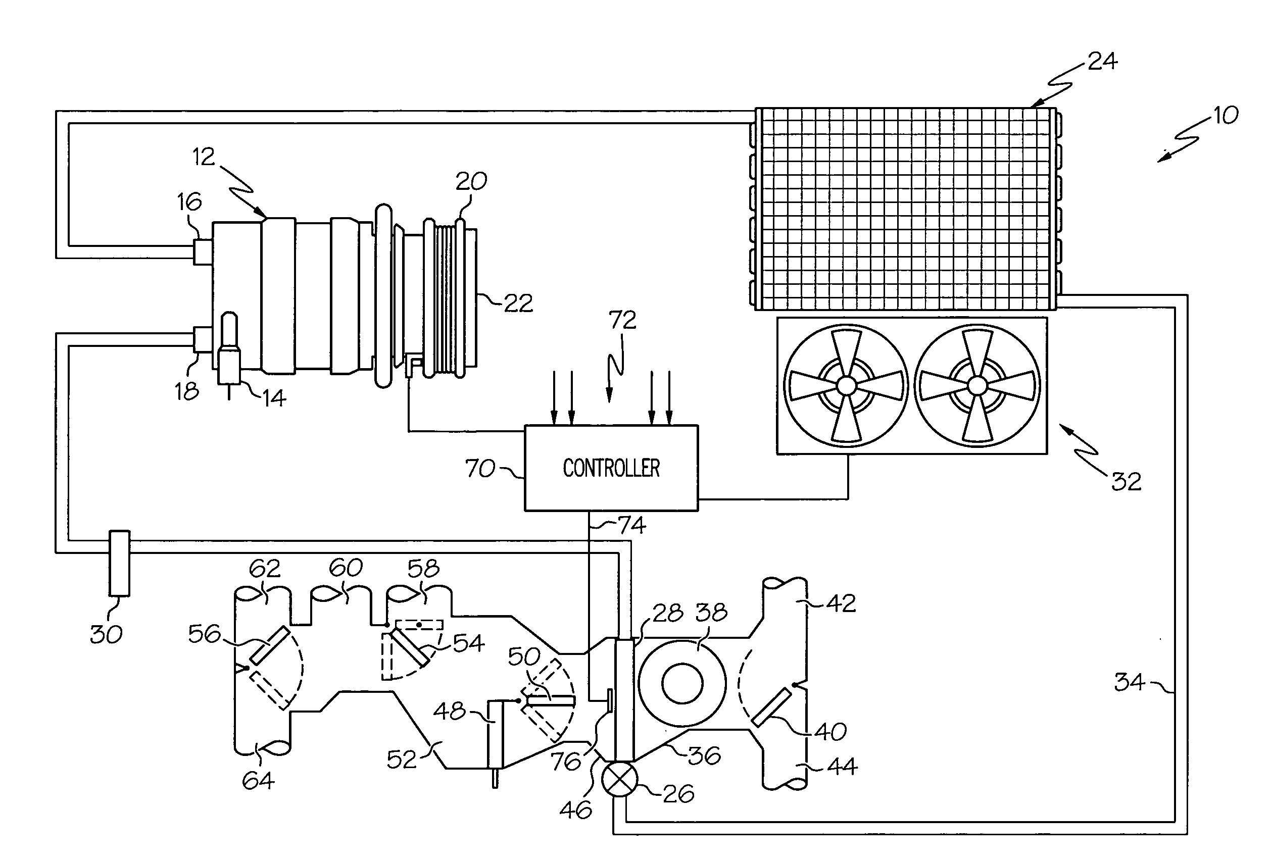
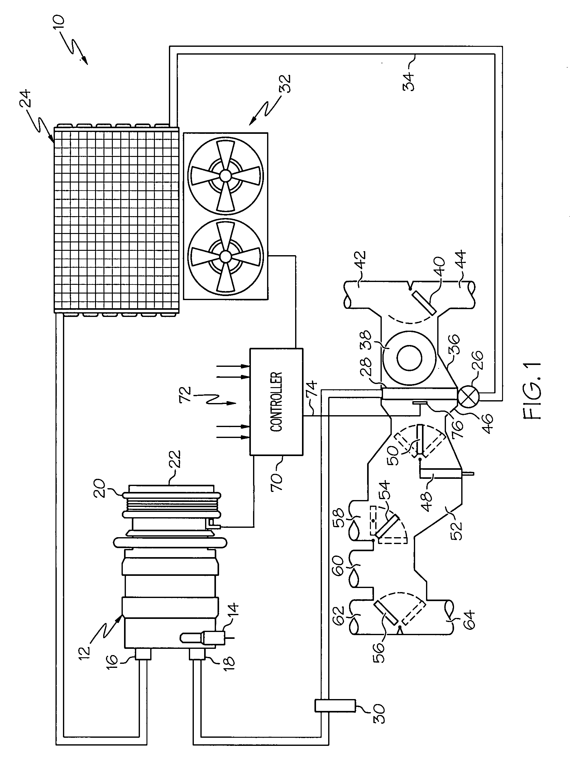
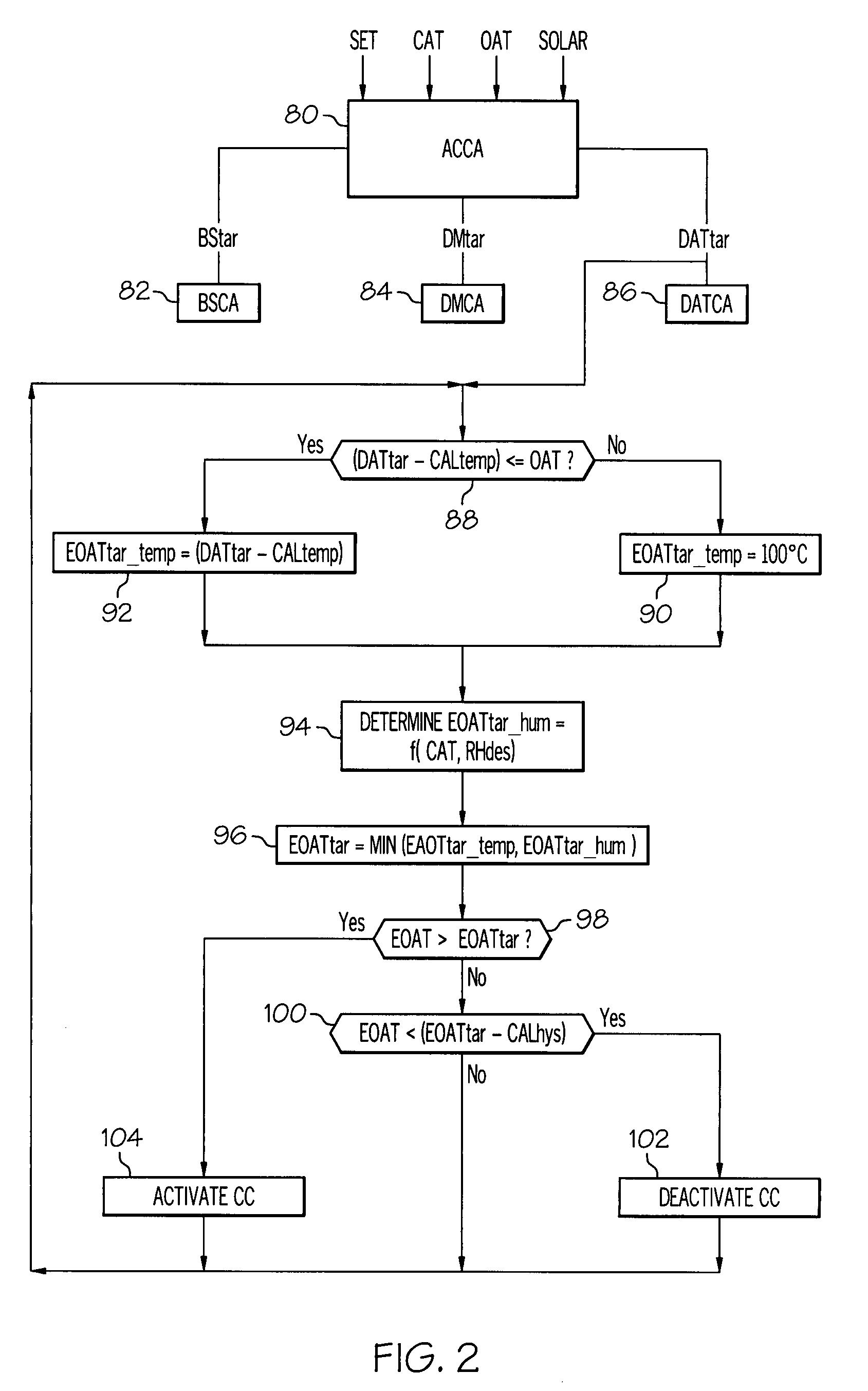
[0004]The present invention provides an improved control methodology for achieving an efficient compressor capacity control with a pneumatically-controlled variable displacement compressor and a compressor clutch that is selectively cycled on and off to minimize series re-heating of conditioned air. Conditioned air is discharged after passing through an evaporator core, and a target value for the evaporator outlet air temperature is determined based on the desired air discharge temperature. The compressor clutch is cycled off when the evaporator outlet air temperature falls below the target value by at least a calibrated amount, and is thereafter cycled on again when the evaporator outlet air temperature rises above the target value. The target value is preferably biased to prevent compressor operation when the desired air discharge temperature exceeds outside air temperature by at least a calibrated amount and to prevent the relative humidity in the air-conditioned space from rising above a desired level.

Problems solved by technology

Nevertheless, using an electronically controlled variable displacement compressor usually results in higher overall system cost because of the modulating control valve and the required control electronics.

Method used


Image

  • Control method for a variable displacement refrigerant compressor in a high-efficiency AC system
  • Control method for a variable displacement refrigerant compressor in a high-efficiency AC system
  • Control method for a variable displacement refrigerant compressor in a high-efficiency AC system

Examples


Embodiment Construction

[0007]The present invention recognizes that the fuel efficiency benefits described in the aforementioned U.S. Pat. No. 6,293,116 to Forrest et al. can be achieved at a reduced system cost by combining a pneumatically-controlled variable displacement compressor (such as shown and described in the U.S. Pat. No. 4,428,718 to Skinner, for example) with a compressor clutch cycle control that comes into play when series re-heating of the conditioned air is required to achieve the desired air discharge temperature. The system cost is reduced because a pneumatically-controlled variable displacement compressor is less expensive to produce than an electronically controlled variable displacement compressor, and the control electronics required to carry out the clutch cycling control are simpler and less expensive than with traditional electronically controlled displacement. Ordinarily, of course, a pneumatically-controlled variable displacement compressor is not cycled on and off during activa...


PUM


Abstract

A high efficiency air conditioning system includes a pneumatically-controlled variable displacement compressor and a compressor clutch that is selectively cycled on and off to minimize series re-heating of conditioned air. Conditioned air is discharged after passing through an evaporator core, and a target value for the evaporator outlet air temperature is determined based on the desired air discharge temperature. The compressor clutch is cycled off when the evaporator outlet air temperature falls below the target value by at least a calibrated amount, and is thereafter cycled on again when the evaporator outlet air temperature rises above the target value. The target value is preferably biased to prevent compressor operation when the desired air discharge temperature exceeds outside air temperature by at least a calibrated amount and to prevent the relative humidity in the air-conditioned space from rising above a desired level.

Description

TECHNICAL FIELD[0001]The present invention relates to a motor vehicle air conditioning system in which the capacity of a refrigerant compressor is controlled for high efficiency, and more particularly to a capacity control method for a variable displacement refrigerant compressor in such an air conditioning system.BACKGROUND OF THE INVENTION[0002]Vehicle fuel efficiency studies have shown that a traditional air conditioning system with a fixed displacement compressor cycled on and off in the usual fashion can account for the consumption of nearly twenty-five gallons of gasoline per vehicle annually. As described in the U.S. Pat. No. 6,293,116 to Forrest et al., however, air conditioning efficiency can be significantly improved by regulating the compressor capacity in a way that eliminates over-dehumidification and minimizes series re-heating of conditioned air. Whereas compressor capacity is traditionally regulated so as maximize cooling by the evaporator without ice formation on th...

Claims


Application Information

Patent Timeline
IPC IPC(8): F25B49/02
CPCB60H1/00735B60H1/00835B60H1/3211B60H2001/3245B60H2001/3261B60H2001/3275
Inventor KADLE, PRASAD S.ZIMA, MARK J.
Owner DELPHI TECH INC
Learn More