Image display device

a display device and image technology, applied in the field of image display devices, can solve the problems of reducing contrast, reducing maximum brightness, and pixels cannot perform a display of more brightness, so as to eliminate burn-in phenomenon, prevent gray scale collapse, and eliminate burn-in phenomenon without lowering contrast

Active Publication Date: 2008-11-27
SAMSUNG DISPLAY CO LTD +1
View PDF3 Cites 16 Cited by
  • Summary
  • Abstract
  • Description
  • Claims
  • Application Information

AI Technical Summary

Benefits of technology

[0009]According to the present invention, in the correction of burn-in, it is possible to prevent the gray scale collapse after correction by preliminarily changing the dynamic range of display data before correction. According to embodiments 1 and 2, it is possible to eliminate the burn-in phenomenon while holding the maximum brightness. Further, according to an embodiment 3, it is possible to eliminate the burn-in phenomenon without lowering the contrast. According to an embodiment 4, it is possible to perform the gamma correction in a compatible manner with the correction of burn-in. According to a fifth embodiment, it is possible to perform the correction as viewed with naked eyes due to the adjustment of correction quantities of R, G, B independently. The present invention is applicable to a display unit as a single unit, a built-in panel in which the display device is incorporated, or a display device of a portable digital assistant.

Problems solved by technology

With the use of such a correction method, however, when the pixels are degraded in spite of a demand for the maximum brightness based on the display data, the pixels cannot perform a display of more brightness.
Accordingly, there arises a drawback that the maximum brightness is lowered, that is, contrast is lowered.

Method used


Image

  • Image display device
  • Image display device
  • Image display device

Examples


embodiment 1

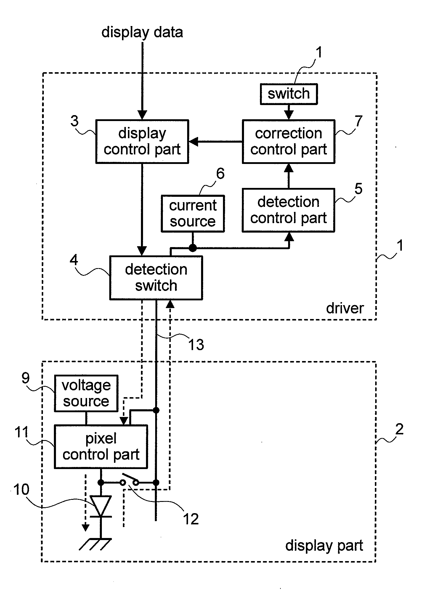
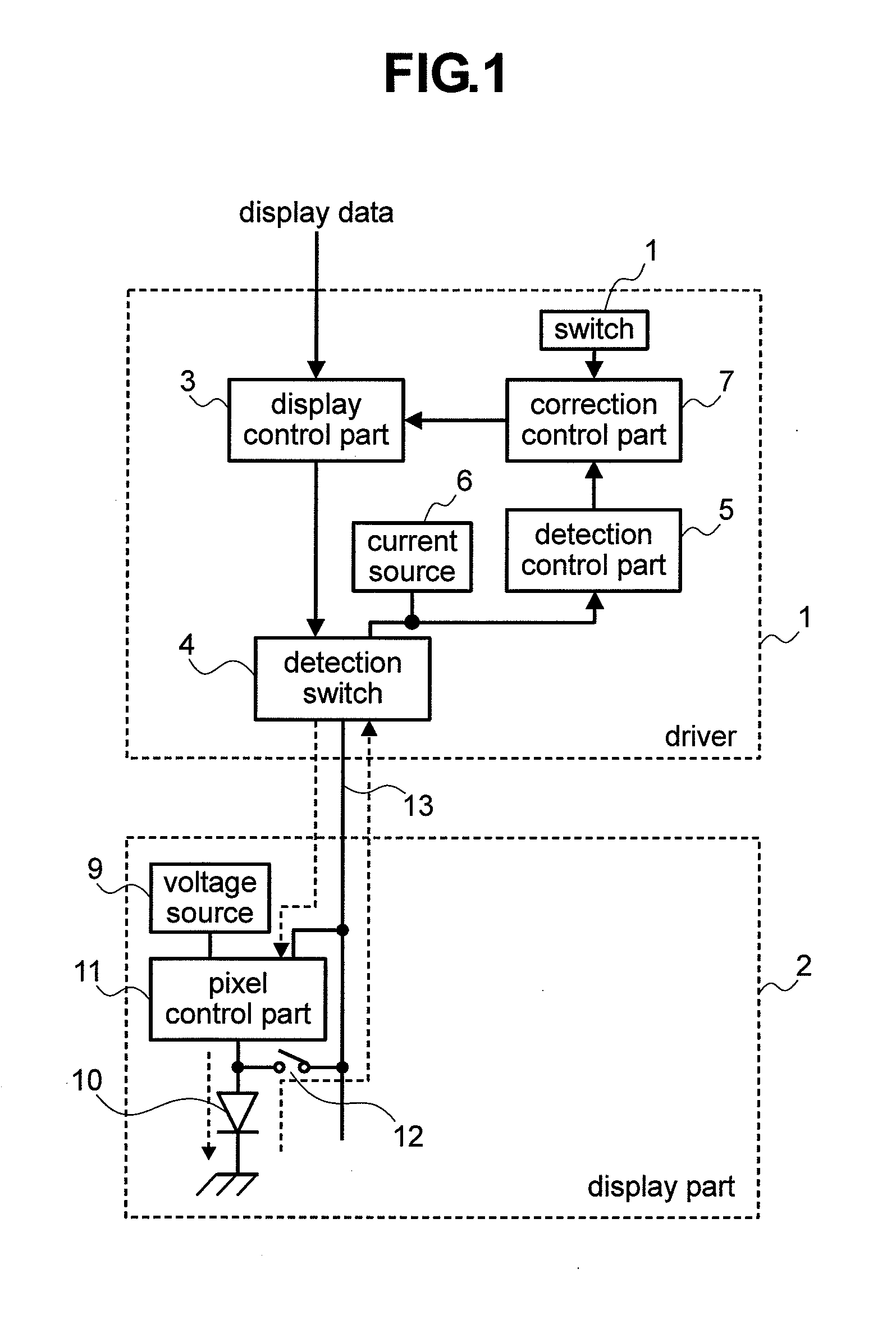
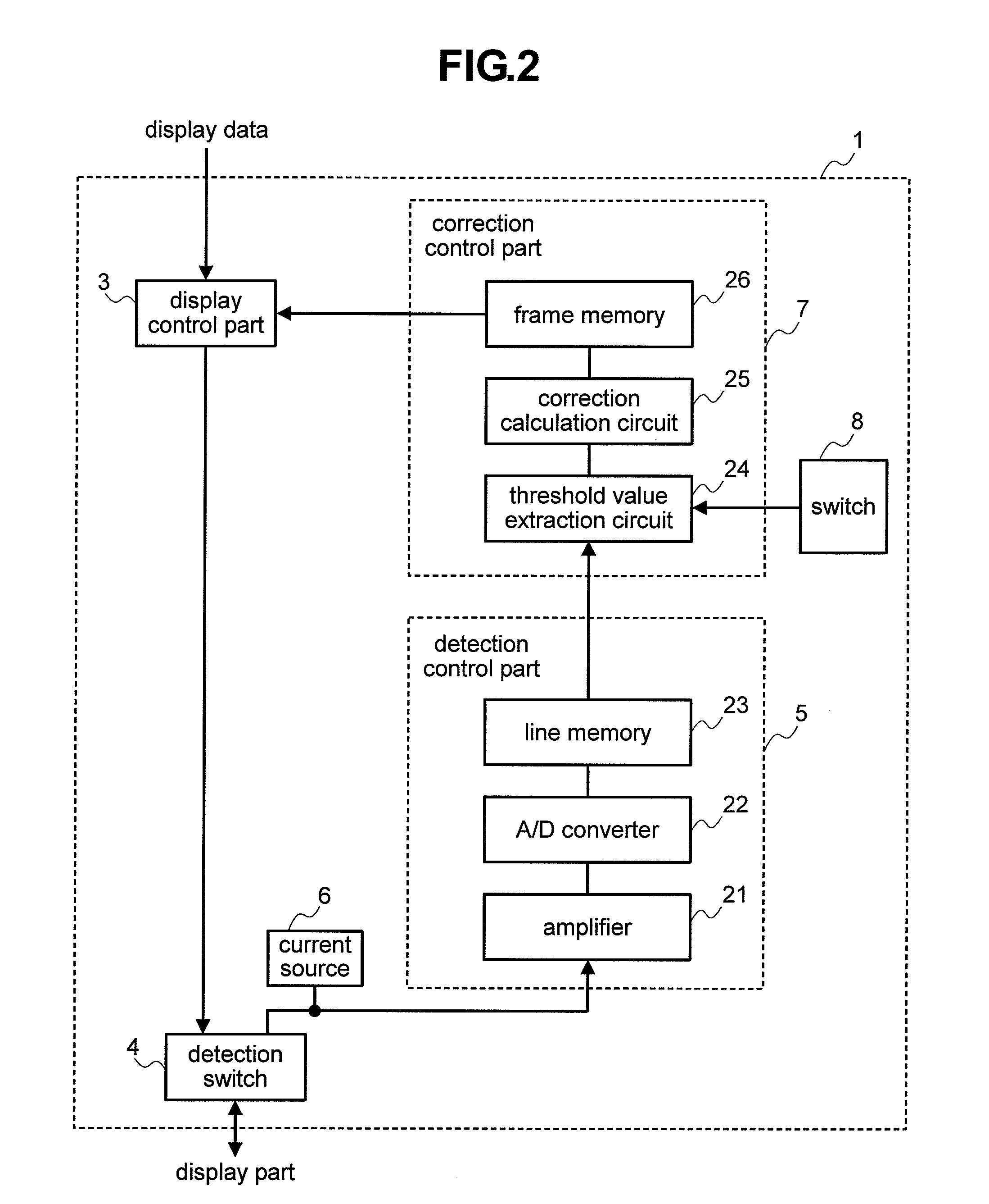
[0024]FIG. 1 is an overall constitutional view of a display panel part. In FIG. 1, the display panel part is constituted of a driver 1 and a display part 2. The driver 1 includes a display control part 3, a detection switch 4, a detection control part 5, a detection-use current source 6, a correction control part 7, and a correction selection switch 8. The display part 2 includes a display-use voltage source 9, display elements 10, pixel control parts 11, and selection switches 12. The driver 1 and the display part 2 are connected with each other using a bus 13. The detection-use current source 6 is provided to a signal line which connects the detection control part 5 and the detection switch 4, and the detection control part 5 detects a voltage change of the display element 10 on the signal line. Display data from the outside is inputted to the display control part 3 of the driver 1. The display control part 3 performs a timing control and a signal control of an input signal. The d...

embodiment 2

[0048]FIG. 10 is an explanatory view of another operation of the correction calculation circuit 25 shown in FIG. 2. The operation explained in conjunction with FIG. 10 differs from the operation of the embodiment 1 explained in conjunction with FIG. 5 with respect to a point that the brightness at the 0th gray scale is not set to the minimum brightness in FIG. 5, while the brightness at the 0th gray scale is set to the minimum brightness in FIG. 10.

[0049]When a solid line 101 shown in FIG. 10 is translated, the power source voltage is set such that the brightness 106 at the 60th gray scale and the brightness 10 at the 63rd gray scale become equal to each other and, at the same time, the brightness 103 which exceeds the maximum brightness is acquired at the 63rd gray scale on the solid line 101. This power source voltage is not changed after being set. After setting of the power source voltage, the brightness 103 on the solid line 101 is lowered to the brightness 104 on the solid lin...

embodiment 3

[0050]FIG. 11 is an explanatory view of another operation of the correction calculation circuit 25 shown in FIG. 2. In the operation of the embodiment 1 explained in conjunction with FIG. 5 or the operation of the embodiment 2 explained in conjunction with FIG. 10, the correction is performed on the solid line 45 or on the solid line 101. The advantage of these corrections lies in that it is sufficient to superimpose the correction-use gray scale to the display data and hence, the circuit can be simplified. However, these corrections have following drawbacks. That is, in the correction on the solid line 45, black assumes the floating state at the 0th gray scale in an initial state and black is gradually deepened due to the correction. Further, in the correction on the solid line 101, although the output brightness is 0 at the 0th gray scale in an initial state, the display data of low gray scales is gradually ignored due to the correction.

[0051]Accordingly, in this embodiment, the c...


PUM


Abstract

With the use of pixel control parts for controlling display elements in response to display data using a display-use voltage source and display control parts for supplying the display data to the pixel control parts, the display data is displayed on a display part. Further, the display data is corrected by detecting states of the display elements. A voltage of the display-use voltage source is preliminarily set to a fixed higher voltage, and a gray scale of the display data is elevated in response to a degradation state of the display element. Accordingly, it is possible to perform a display while maintaining the maximum brightness even when the display element is degraded. Further, the contrast can be maintained by correcting the gray scales of the display data by performing only the digital calculation.

Description

CLAIM OF PRIORITY[0001]The present application claims priority from Japanese application serial no. 2007-136513 filed on May 23, 2007, the content of which is hereby incorporated by reference into this application.BACKGROUND OF THE INVENTION[0002]1. Field of the Invention[0003]The present invention relates to an image display device which can control brightness in response to a quantity of electric current which is applied to display elements or a light emission time, and more particularly to an image display device having self-luminous light elements represented by organic EL (Electro Luminescence) elements or organic light emitting diodes (OLED) as the display elements.[0004]2. Description of the Related Art[0005]Thanks to the popularization of various information processing devices, various image display devices exist corresponding to roles. Among these image display devices, a self-luminous image display device has been attracting attentions, and an organic EL display has been a...

Claims


Application Information

Patent Timeline
Patent Type & Authority Applications(United States)
IPC IPC(8): G09G5/10
CPCG09G3/3233G09G2310/06G09G2320/0271G09G2320/0285G09G2320/0295G09G2320/043
Inventor ISHII, MASATOKASAI, NARUHIKOMIYAMOTO, MITSUHIDEKOHNO, TOHRUAKIMOTO, HAJIME
Owner SAMSUNG DISPLAY CO LTD
Why Eureka
Try Eureka