Easily removable mower cutting deck

a mower and cutting board technology, applied in the field of lawn mowers, can solve the problems of difficult to remove or install and the space under the frame of the mower in which the cutting board is carried is quite limited, and it is not easy to achieve the effect of removing or installing the mower deck in this tight or limited spa

Inactive Publication Date: 2008-12-04
TORO CO THE
View PDF23 Cites 10 Cited by
  • Summary
  • Abstract
  • Description
  • Claims
  • Application Information

AI Technical Summary

Benefits of technology

[0010]Another aspect of this invention relates to a lawn mower that comprises a frame supported for movement over the ground by a plurality of ground engaging wheels. A rotary cutting deck is carried beneath the frame between front and rear ground engaging wheels. A suspension system suspends the cutting deck beneath the frame. The suspension system connects to the cutting deck at three connections arranged in a triangular configuration. One connection comprises a pivot pin that must be released and pulled from the cutting deck and the other two connections comprise hooks on the cutting deck that must be unhooked from the suspension system to completely disconnect the cutting deck from the suspension system. A height of cut adjustment system is operatively coupled to the suspension system in a location that does not interfere with removal of the cutting deck such that the cutting deck can be disconnected and removed from the deck suspension system by removing and releasing the pivot pin, unhooking the hooks, and then dropping the cutting deck from the deck suspension system without having to manually reposition any components in the height of cut adjustment system.

Problems solved by technology

However, the space beneath the frame of the mower in which the cutting deck is carried is quite limited.
The task of removing or installing the mower deck in this tight or limited space is difficult.
This is not an easy task in most cases.
While Schmidt's cutting deck is theoretically easier to remove than other known cutting decks, removing the deck is not quite as simple as it appears.
The reason for this is that part of the height of cut adjustment mechanism obstructs easy removal of the cutting deck from beneath the frame of the mower even after the quick release pins are removed.

Method used


Image

  • Easily removable mower cutting deck
  • Easily removable mower cutting deck
  • Easily removable mower cutting deck

Examples


Embodiment Construction

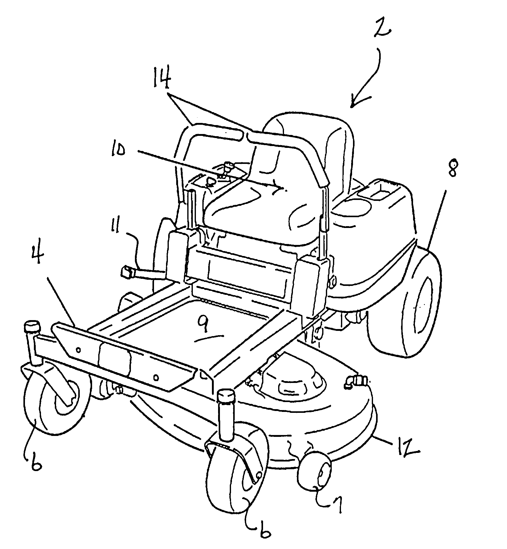
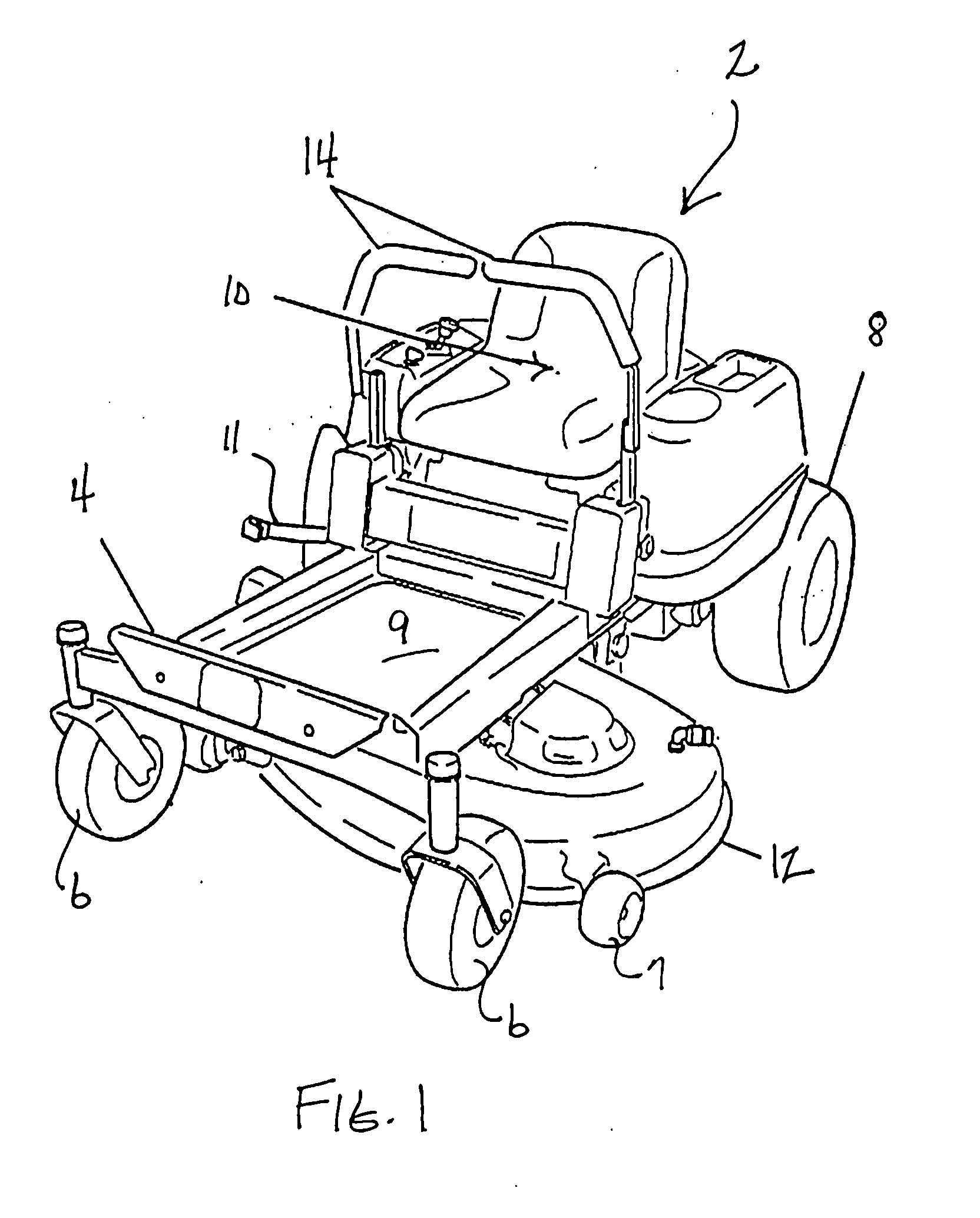
[0022]FIG. 1 illustrates an outdoor power equipment unit comprising a riding mower 2. Mower 2 includes a frame 4 supported for movement over the ground by a pair of front caster wheels 6 and a pair of rear drive wheels 8. An operator's station defined by a floorboard 9 and a seat 10 is provided on frame 4 for supporting a seated operator. An internal combustion engine or the like (not shown) is provided on the rear of frame 4 behind seat 10 to power mower 2.

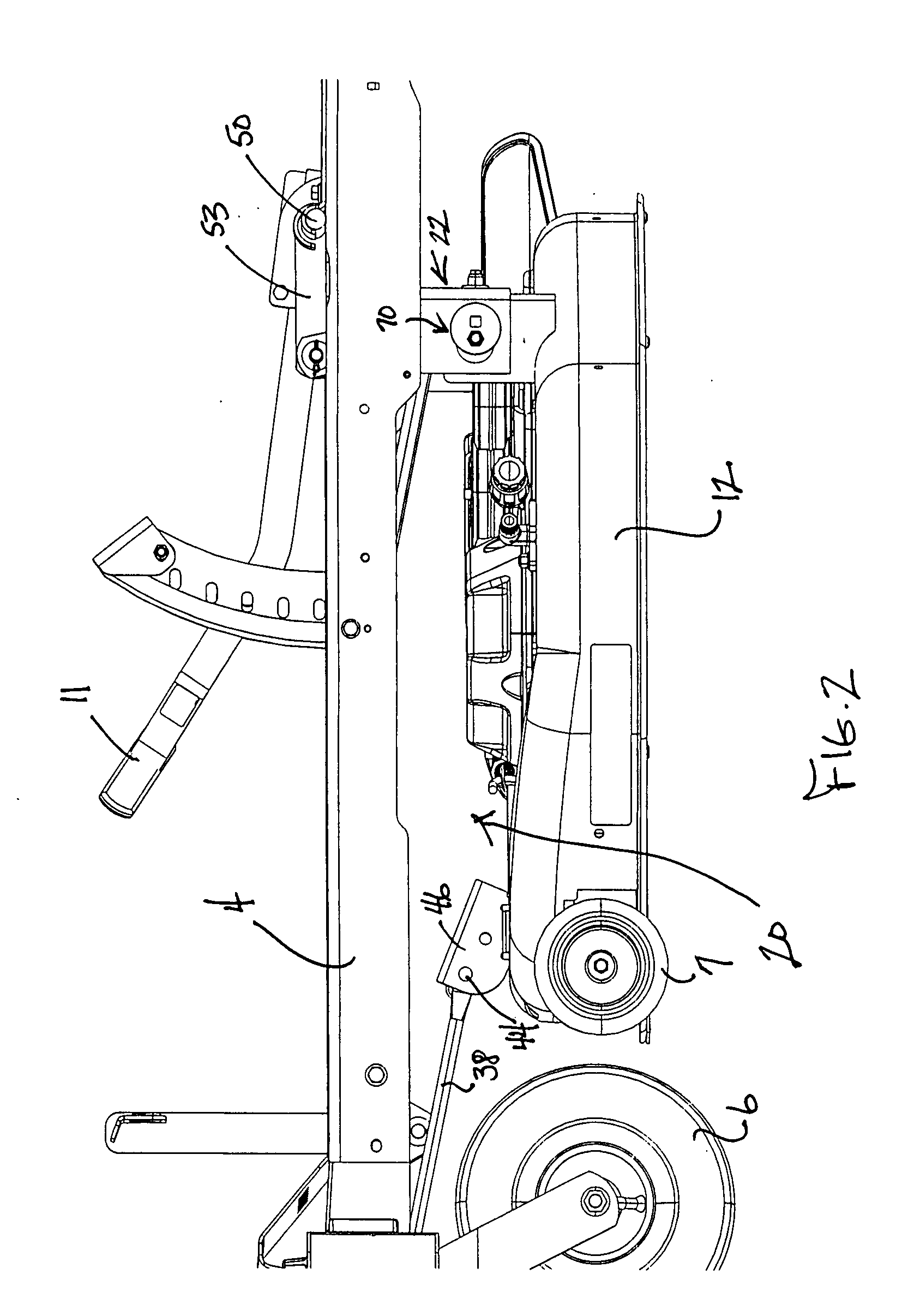
[0023]A cutting deck 12 is mounted beneath frame 4 between front caster wheels 6 and rear drive wheels 8 for mowing grass or the like. Mower 2 includes two control sticks 14 for allowing the operator to cause mower 2 to move in forward and reverse and to steer mower 2. Mower 2 as depicted herein is for illustrative purposes only. Mower 2 may have different forms, numbers and arrangements of ground engaging wheels, drive and steering systems, etc. This invention relates to a suspension system 20 for suspending cutting deck 12 bene...


PUM


Abstract

A rotary cutting deck is suspended from the frame of a lawn mower to hang beneath the frame of the mower between the front and rear ground engaging wheels of the mower. A single front pull arm is pinned by a pivot pin to the front of the cutting deck. This pivot pin can be easily released and pulled by removing a single hairclip pin or cotter pin. The rear of the cutting deck is hung by two downwardly facing suspension hooks onto the cross rod of a pivotal hanger. After the front pull arm is disconnected from the front of the cutting deck, the operator lifts up the rear of the cutting deck to unhook the suspension hooks, pulls the cutting deck slightly rearwardly, and then lowers the cutting deck to the ground to allow the cutting deck to be slid out from underneath the mower after also removing any deck drive belt or similar cutting blade drive system. This can be easily and quickly done.

Description

TECHNICAL FIELD[0001]This invention relates to a lawn mower having a cutting deck carried beneath the frame of the mower between the front and rear ground engaging wheels of the mower. More particularly, this invention relates to a cutting deck that can be quickly and easily installed on or removed from the mower.BACKGROUND OF THE INVENTION[0002]Lawn mowers that carry a large rotary cutting deck beneath the frame of the mower are well known. The cutting deck is often positioned between a pair of front wheels and a pair of rear drive wheels. When the mower is a riding mower in which an operator sits on a seat located on the frame of the mower, the cutting deck is often positioned beneath at least a portion of the operator's body. This type of cutting deck is sometimes referred to as a belly mounted cutting deck or a mid-mount cutting deck.[0003]Cutting decks of this type usually have a plurality of rotary cutting blades disposed across the width of the deck. The cutting blades rotate...

Claims


Application Information

Patent Timeline
Patent Type & Authority Applications(United States)
IPC IPC(8): A01D34/00
CPCA01D34/82A01D34/64Y10S56/22
Inventor PORTER, TODD A.DINEEN, GREGORY L.
Owner TORO CO THE
Why Eureka
Try Eureka