Inhaler vaporizer

a technology of inhaler and vaporizer, which is applied in the direction of packaging, other medical devices, coatings, etc., can solve the problem of long treatment time of such infections

Inactive Publication Date: 2008-12-04
SVEHAUG OSWALD C +1
View PDF4 Cites 11 Cited by
  • Summary
  • Abstract
  • Description
  • Claims
  • Application Information

AI Technical Summary

Problems solved by technology

Even with the intervention of health professionals at this time, the treatment of such infections can be lengthy and generally entails lengthy bed rest.
Not only is this a health concern, but a monetary concern as well because prescription drugs may be expensive and the amount of time lost during the incubation of such infections can affect income, both to the patient and to family and personnel at work.

Method used


Image

  • Inhaler vaporizer
  • Inhaler vaporizer
  • Inhaler vaporizer

Examples


first embodiment

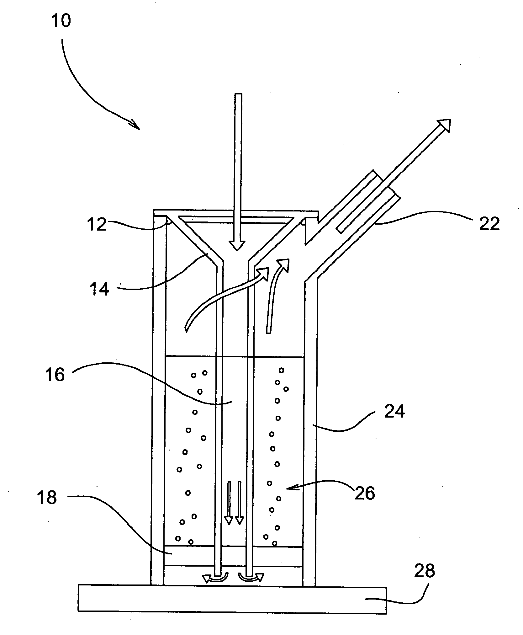
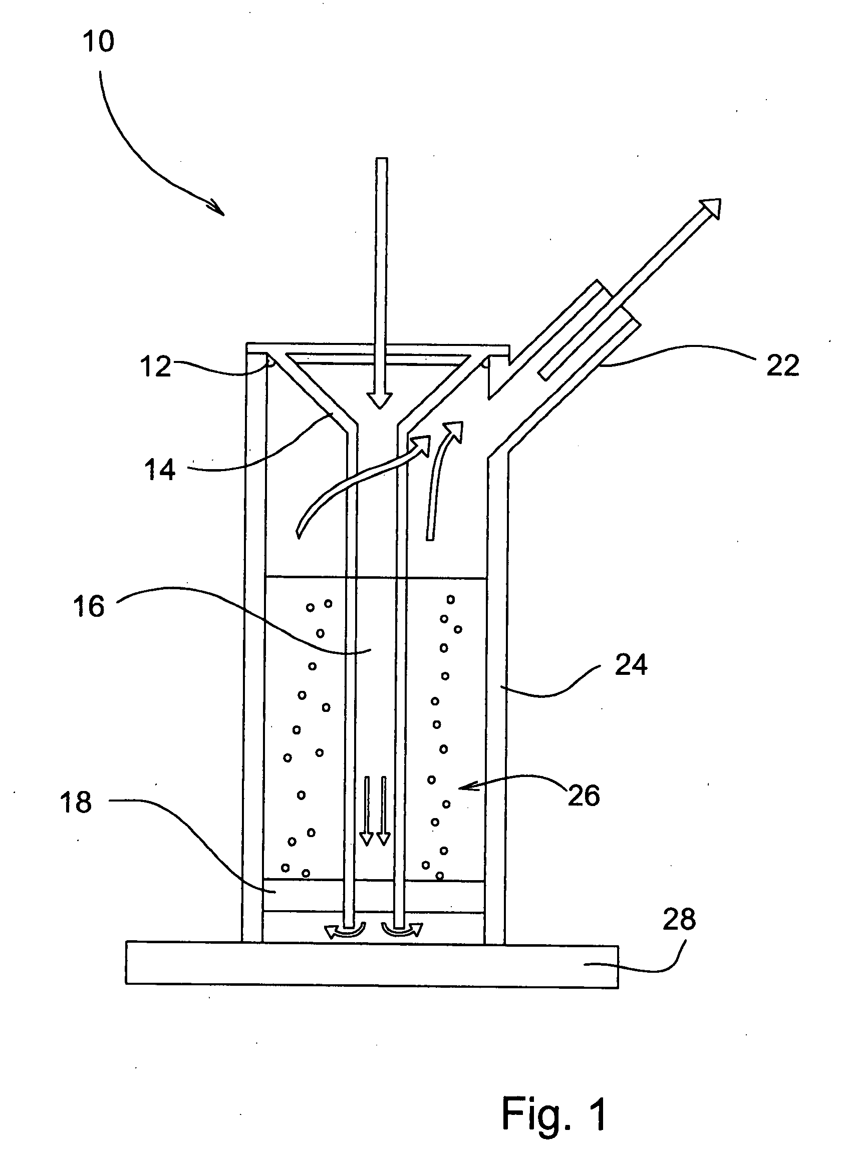
[0029]Referring now to the drawings, wherein similar parts are identified by like reference numerals, FIG. 1 shows a front cross sectional view of the novel inhaler vaporizer 10 with an o ring 12 sealing the perimeter of the funnel cone 14 and the of the body 24 of the inhaler vaporizer 10. The air is drawn into the funnel stem 16 and drawn into the main body 24 of the inhaler vaporizer 10 when suction is applied through the mouthpiece 22 of the inhaler vaporizer 10. The air is pulled through the disc 18 as suction is applied on the mouthpiece 22. The aerated alcohol liquid 26 forms miniscule droplets and vapors of the alcohol which is inhaled in through the mouthpiece 22.

embodiment 30

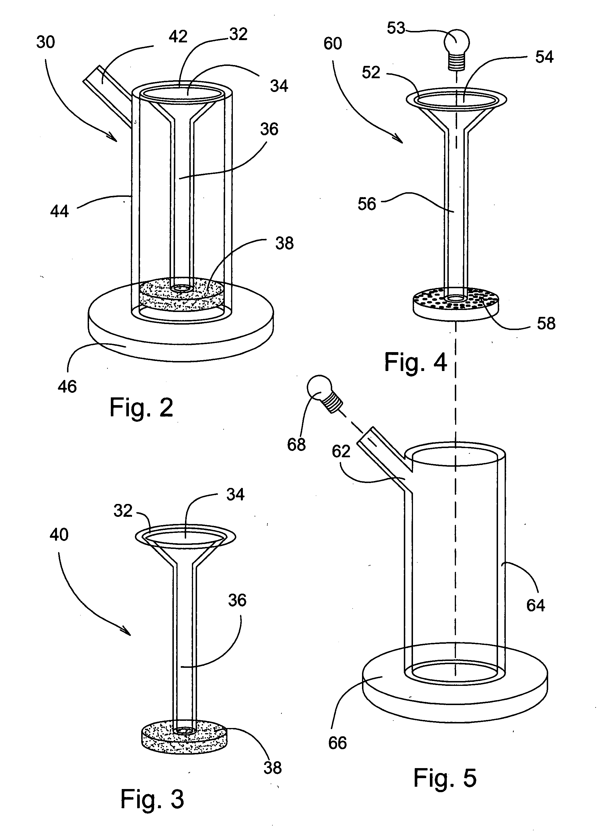
[0030]Referring now to FIG. 2, a side elevational view of the alternate embodiment 30, the mouth piece 42 is seen located on the side of the main body 44 of the inhaler vaporizer 30. The main body of the inhaler 44 is attached to the base of the body 46. The o ring 32 seals the funnel cone 34 to the main body 44 of the inhaler vaporizer 30. The funnel stem 36 passes through the porous disc 38.

[0031]Referring now to FIG. 3, a side elevational view of the y-shaped internal portion 40 of the first embodiment of the inhaler vaporizer. The gasket 32 is seen located on the funnel portion 34 of the y-shaped internal portion 40 of the inhaler vaporizer. The funnel stem 36 passes through the porous disc 38.

second embodiment

[0032]Referring now to FIG. 4, in the inhaler vaporizer, the O-ring 52 is shown on the funnel cone 54 portion of the y-shaped internal portion 40 of the inhaler vaporizer. The funnel stem 56 passes through the disk of non-porous material 58 which has a plurality of small holes. An optional stopper plug 53 may be used to store the device, with or without liquid therein.

[0033]Referring now to FIG. 5, the mouthpiece 62 of the inhaler vaporizer attaches to the body 64 of the inhaler vaporizer which, in turn is attached to a base plate 66. An optional stopper plug 68 may be used to store the device, with or without liquid therein, and optionally with or without stopper plug 53.

[0034]Referring now to FIG. 6, there is shown a side view of the first embodiment of the inhaler vaporizer 30. The O-ring 32 forms a seal between the funnel cone 34 and the main body 44 of the inhaler vaporizer 30. The funnel stem 36 passes through the disk composed of inert porous material 38.

[0035]As illustrated ...


PUM


Abstract

An inhaler vaporizer consists of two parts, the first part consisting of a funnel with a top portion, a “Y” portion and a disc portion made of a porous material or a non-porous material with a multiplicity of small holes. This part is inserted into a main body portion consisting of a main body, mouthpiece and base. The internal “Y” portion is sealed to the main body portion by an O-ring. Ethyl alcohol is poured into the main body of the inhaler vaporizer, and air is drawn into the inhaler vaporizer by applying suction through the mouthpiece. This air is drawn into the “Y” cone, passes through the “Y” stem tubular portion to the bottom of the body portion of the inhaler vaporizer. The air is drawn through the alcohol, vaporizing the alcohol in the process and is then inhaled through the mouthpiece into the mouth, throat, and lungs where it interacts with affected tissue.

Description

FIELD OF THE INVENTION[0001]The present inhaler vaporizer generally relates to the field of devices for the treatment of colds, sore throats, influenza, and pulmonary infections. More specifically, this inhaler vaporizer device deals with a means by which these and other infections may be treated using an inhaler vaporizer to employ alcohol and water vapor in a safe and effective manner.DESCRIPTION OF THE RELATED ART[0002]Traditional treatment regimes for lung, throat, sinus and bronchial infections involve getting a prescription from a health professional, generally after the infection has become worse when nothing available on the market is effective. Even with the intervention of health professionals at this time, the treatment of such infections can be lengthy and generally entails lengthy bed rest. Not only is this a health concern, but a monetary concern as well because prescription drugs may be expensive and the amount of time lost during the incubation of such infections can...

Claims


Application Information

Patent Timeline
Patent Type & Authority Applications(United States)
IPC IPC(8): A61M16/00
CPCA61M11/02A61M16/105A61M2205/75A61M11/003A61M16/107
Inventor SVEHAUG, OSWALD C.SVEHAUG, JUANA
Owner SVEHAUG OSWALD C
Why Eureka
Try Eureka