
Rfid Tag

a technology of rfid tags and tags, applied in secondary cells, cell components, instruments, etc., can solve the problems of reducing the capacity of rechargeable batteries, unable to conduct the function of ic cards, and long charging period of ic cards

Inactive Publication Date: 2008-12-04
NEC CORP
View PDF7 Cites 63 Cited by
  • Summary
  • Abstract
  • Description
  • Claims
  • Application Information

AI Technical Summary

Benefits of technology

[0026]In accordance with the present invention, there is provided an RFID tag which is thin, lightweight, and suitable to be carried about, which is foldable, and which includes a power source.

Problems solved by technology

However, an IC card with a primary battery therein has a problem in which when the end of the battery life comes, the IC card does not conduct its function.
However, when the rechargeable battery described above is employed, the charging thereof takes a long period of time, for example, at least one hour.
Also, when two years or more lapse, the rechargeable battery is greatly lowered in its capacity; the charging is frequently required unless the battery is replaced.
However, the thin-film lithium coin battery, the rechargeable lithium-ion battery, and the rechargeable nickel-hydrogen battery described above require a thickness equal to or more than one millimeter, and hence it is not possible to produce an IC card of the international standard size.
In the present state of the art, although there exists a thin-film capacitor as a power source device which can be installed in a card with a thickness of 0.76 mm, this has a problem of a small storage capacity.
However, the thin-film capacitor, the lithium coin battery, and the conventional rechargeable lithium-ion battery are too stiff to be bent.
Hence, there exists a problem that the power sources described above cannot be adopted for the RFID tag and the contactless IC card which is put in the situation wherein the tag and the card are bent.Patent Document 1: Japanese Patent Laid-Open Publication Ser. No. Hei-7-262333Patent Document 2: International Publication Ser. No. WO01 / 97300Patent Document 3: Japanese Patent Laid-Open Publication Ser. No. 2002-151084Patent Document 4: Japanese Patent Laid-Open Publication Ser. No. 2002-304996Patent Document 5: Japanese Patent Laid-Open Publication Ser. No. 2003-308839

Method used


Image

  • Rfid Tag
  • Rfid Tag
  • Rfid Tag

Examples


examples

(RFID Tag Production Example 1)

[0093]Next, description will be given of a production example of an RFID tag according to the present embodiment.

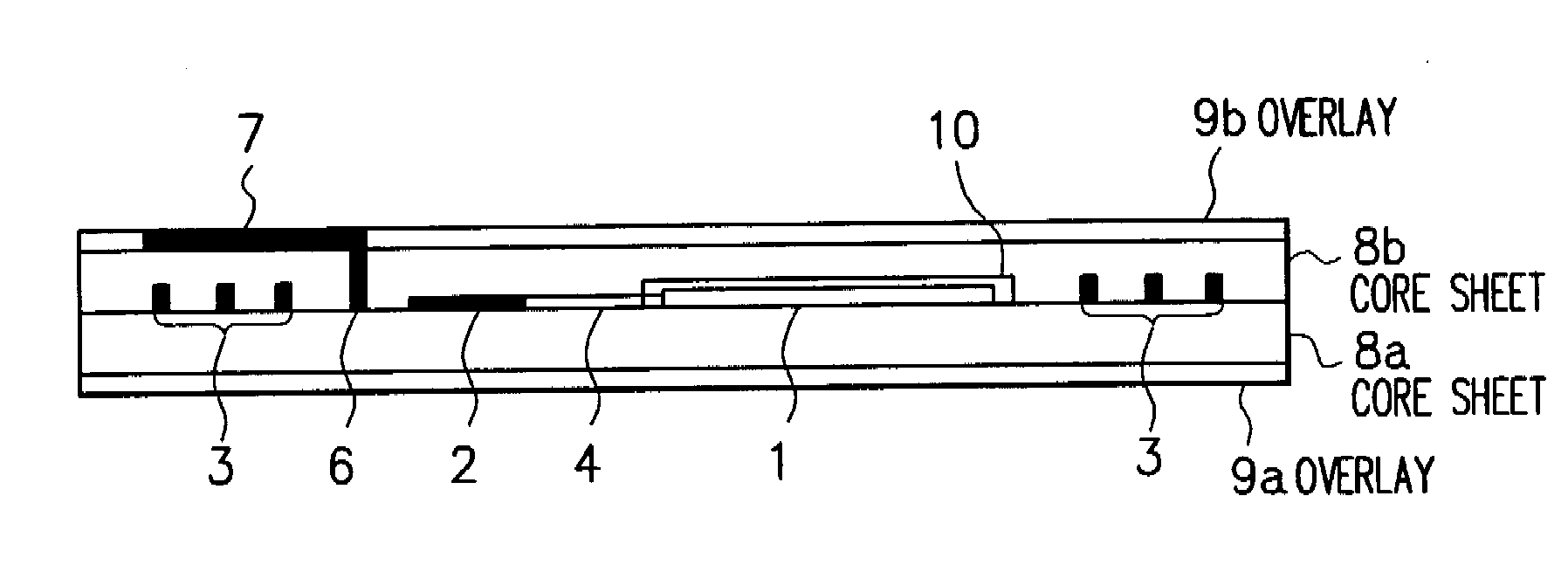
[0094]An IC card as an RFID tag in a cross-sectional configuration shown in FIG. 1 is attained as follows.

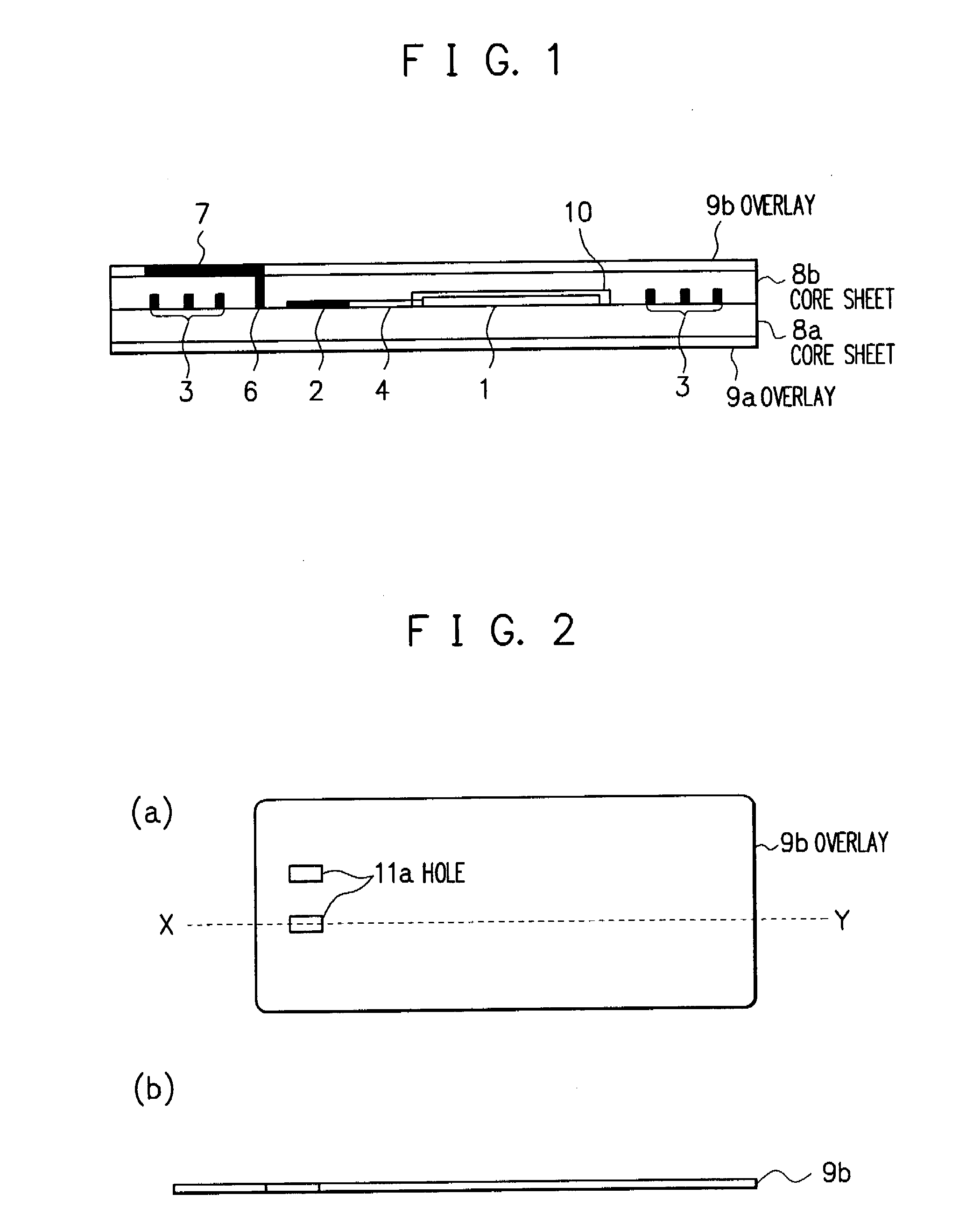
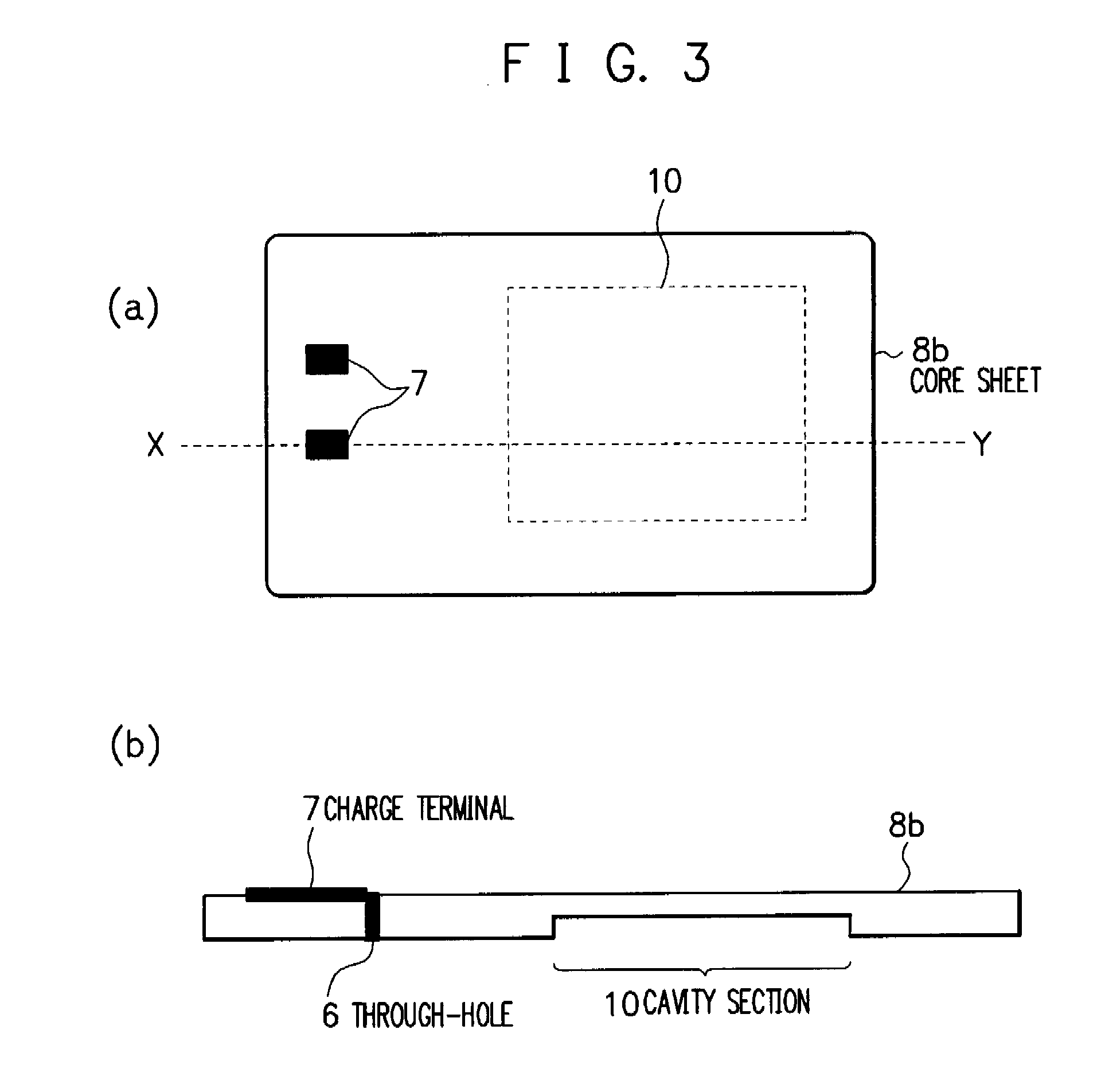
[0095]First, there are prepared a 0.1 mm thick overlay 9b made of PVC, a 0.28 mm thick PVC core sheet 8b in which a though hole 6 for charge wiring and charge terminals 7 are arranged and which includes a cavity section 10 to store an organic radical battery 1; a 0.28 mm thick PVC core sheet 8a in which the organic radical battery 1, an IC module 2, an antenna 3, leads 4, and charge wiring 5 are disposed; and a 1.0 mm thick PVC overlay 9a. Thereafter, the overlay 9a, the core sheet 8a, the core sheet 8b, and the overlay 9a are laminated in this order from the bottom and are thermally crimped (120° C., pressure of 2 kg / cm2, 2 min). As a result, an IC card shown in FIG. 1 is completely produced.

(RFID Tag Production Example 2)

[0096]An IC ca...


PUM


Abstract

To provide an RFID tag including therein a lightweight, thin, reusable by charging, and foldable power source. In an RFID tag including an IC module 2, an antenna 3, and a power source and with a thickness of 0.9 mm or less, there is included an organic radical battery with a thickness of 0.7 mm or less as the power source.

Description

TECHNICAL FIELD[0001]The present invention relates to a RFID tag including an Integrated Circuit (IC) module, an antenna, and a power source, and in particular, to an RFID tag including a chargeable and dischargeable secondary battery as a power source.RELATED ART[0002]As for the RFID tag (a generic name of a wireless device employed for Radio Frequency Identification (RFID)), an IC card which is held by a person and which conducts communication using an electromagnetic wave with a reader-writer (reading / writing) device and the like is called a contactless IC card. The contactless IC card basically includes a plastic card and an IC module and an antenna which are disposed in the plastic card. Between the contactless IC card and the reader-writer device for the IC card, supply of power, a clock signal, and the like as well as input and output of information such as data and commands are carried out by using an electromagnetic wave.[0003]Also, some contactless IC cards include a power...

Claims


Application Information

Patent Timeline
IPC IPC(8): G08B13/22B42D25/305G06K19/00G06K19/07G06K19/077H01M4/60H01M50/193
CPCG06K19/0702G06K19/07749H01M2/08H01M2/1066H01M2/1094H01M4/60H01M4/604H01M6/40H01M10/052H01M10/425H01M10/486Y02E60/122Y02E60/10H01M50/24H01M50/193
Inventor IWASA, SHIGEYUKIMORIOKA, YUKIKOSUGURO, MASAHIROKUSACHI, YUKIIRIYAMA, JIRONAKAHARA, KENTAROMIURA, SADAHIKO
Owner NEC CORP
Features
  • Generate Ideas
  • Intellectual Property
  • Life Sciences
  • Materials
  • Tech Scout
  • Unparalleled Data Quality
  • Higher Quality Content
  • 60% Fewer Hallucinations
Learn More