Developing agent circulation system and image forming apparatus using same

a circulation system and development agent technology, applied in electrographic process apparatus, instruments, optics, etc., can solve the problems of insufficient amount of developing agent transported, degrading image quality, and too much toner being refilled

Inactive Publication Date: 2008-12-04
RICOH KK
View PDF18 Cites 23 Cited by
  • Summary
  • Abstract
  • Description
  • Claims
  • Application Information

AI Technical Summary

Problems solved by technology

A drawback of such conventional development unit is that there is a possibility that too much toner may be refilled because such agitation is conducted in a relatively short time.
If the refilled toner is carried up to the developing sleeve when not effectively dispersed, fogging and toner scattering may occur, degrading image quality.
Any leakage of air reduces the air pressure used for transporting the developing agent, which can cause the amount of developing agent transported to be insufficient.
Further, if the air backflows to the agent storage unit (i.e., pressure is applied to the agent storage unit), discharge of the developing agent from the agent storage unit to the agent supply unit is blocked by such backflowing air, again reducing the amount of developing agent discharged as well as causing that amount to fluctuate uncontrollably.
Although the rotary feeder can reliably supply the developing agent, air backflow to the agent supply unit may occur due to insufficient sealing of the agent supply unit.
However, such configuration may accelerate degradation of the rotor and the stator over time, through scraping of the rotor and the stator or the like, which is undesirable.
Because the carrier component of the developing agent is made of harder material than the toner, such as iron, ferrite, or the like, such vane-impressing configuration does not provide adequate durability.

Method used


Image

  • Developing agent circulation system and image forming apparatus using same
  • Developing agent circulation system and image forming apparatus using same
  • Developing agent circulation system and image forming apparatus using same

Examples


Embodiment Construction

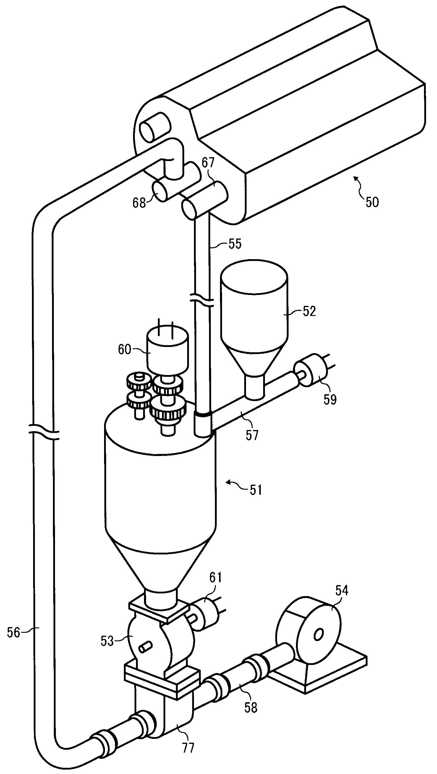
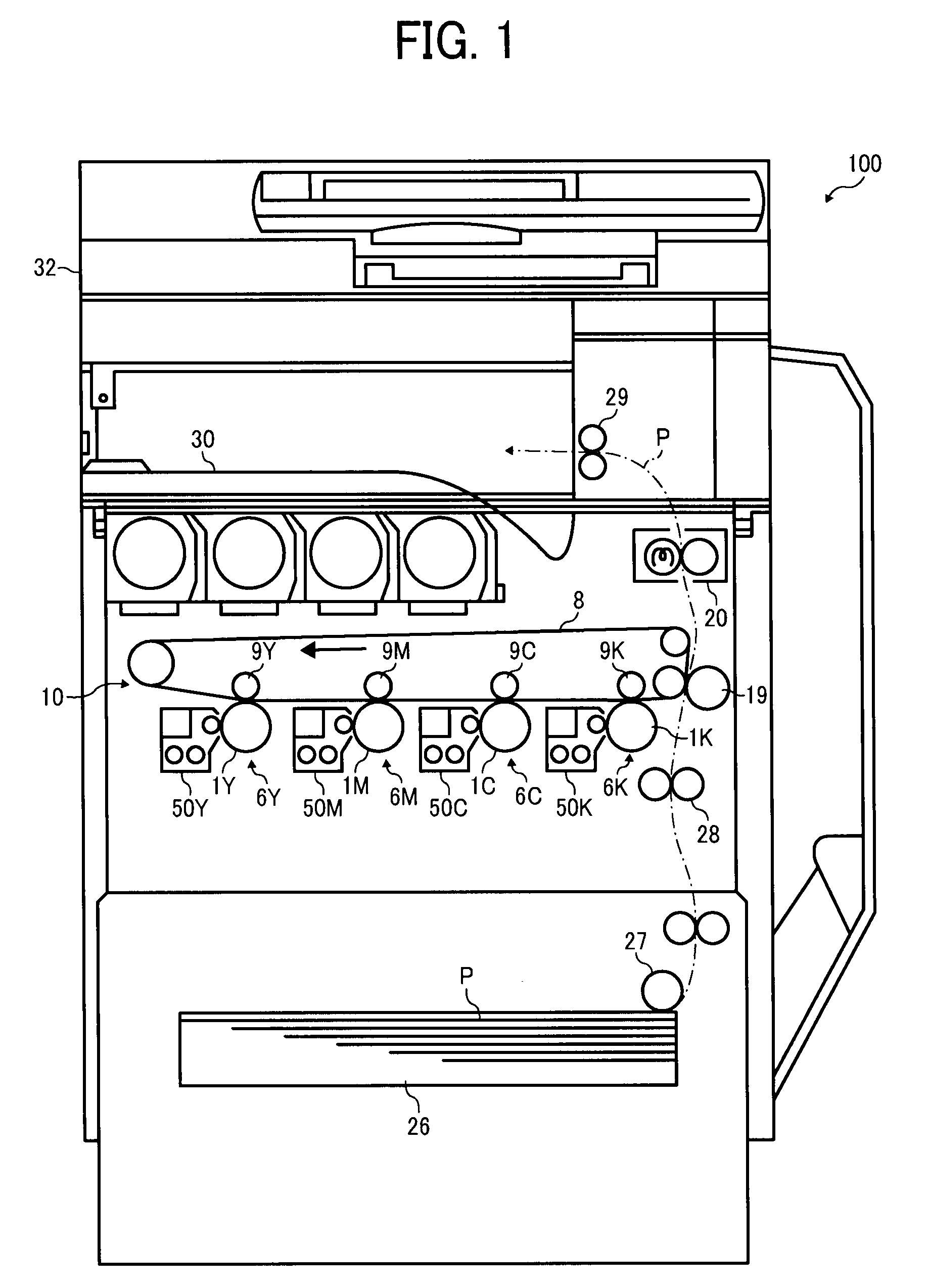
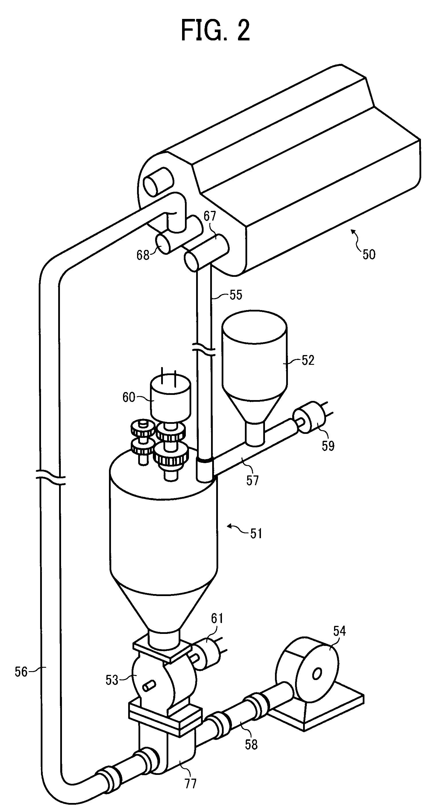
[0028]A description is now given of exemplary embodiments of the present invention. It should be noted that although such terms as first, second, etc. may be used herein to describe various elements, components, regions, layers and / or sections, it should be understood that such elements, components, regions, layers and / or sections are not limited thereby because such terms are relative, that is, used only to distinguish one element, component, region, layer or section from another region, layer or section. Thus, for example, a first element, component, region, layer or section discussed below could be termed a second element, component, region, layer or section without departing from the teachings of the present invention.

[0029]In addition, it should be noted that the terminology used herein is for the purpose of describing particular embodiments only and is not intended to be limiting of the present invention. Thus, for example, as used herein, the singular forms “a”, “an” and “the...


PUM


Abstract

A development agent circulation unit includes a development unit, an agitation unit, and a rotary feeder. The development unit develops a latent image on an image carrier using a developing agent. The agitation unit agitates developing agent recovered from the development unit. The rotary feeder receives the developing agent from the agitation unit and discharges the developing agent in predetermined discrete amounts. The discharged developing agent is transported to the development unit using a gas stream. The rotary feeder includes a rotor and a stator having a clearance “t” between the rotor and the stator. The clearance “t” satisfies a relation “t<2D” where D denotes a developing agent particle diameter, and a toner particle diameter dt of a toner particle of the developing agent and a carrier particle diameter dc of a carrier particle of the developing agent satisfy a relation D=dc+2dt.

Description

CROSS-REFERENCE TO RELATED APPLICATIONS[0001]This application claims priority from Japanese Patent Application No. 2007-147305, filed on Jun. 1, 2007 in the Japan Patent Office, the entire contents of which are hereby incorporated by reference herein.BACKGROUND OF THE INVENTION[0002]1. Field of the Invention[0003]The present disclosure generally relates to a development unit for developing an electrostatic latent image on an image carrier, and an image forming apparatus employing the development unit.[0004]2. Description of the Background Art[0005]Typically, an image forming apparatus using electrophotography employs a development unit to develop an electrostatic latent image formed on an image carrier using a developing agent, such as a two-component developing agent mainly composed of toner and carrier. The development unit has an internal configuration designed to recover the developing agent, which consumes toner component at a development area for a development process, to mix ...

Claims


Application Information

Patent Timeline
Patent Type & Authority Applications(United States)
IPC IPC(8): G03G21/00
CPCG03G2215/0685G03G2215/0819G03G15/0877G03G15/087G03G15/0879G03G2215/0841
Inventor MATSUMOTO, JUNICHIIWATA, NOBUOKATOH, NATSUMIOHMURA, TOMOYA
Owner RICOH KK
Why Eureka
Try Eureka