
Location Estimation of Wireless Terminals Through Pattern Matching of Signal-Strength Differentials

a wireless terminal and signal strength technology, applied in the field of telecommunications, can solve the problems of not being able to readily ascertain the location of interested parties, not being able to meet the requirements of higher accuracy, generally not acceptable for applications, emergency services dispatch, etc., and achieves the effect of reducing the number of data points, doubling the variance of random measurement noise, and common bias

Inactive Publication Date: 2008-12-04
POLARIS WIRELESS
View PDF9 Cites 80 Cited by
  • Summary
  • Abstract
  • Description
  • Claims
  • Application Information

AI Technical Summary

Benefits of technology

[0025]A disadvantage of this approach is that the common bias is eliminated at the expense of (1) doubling the variance of the random measurement noise, and (b) by reducing the number of data points to match by one. Furthermore, the pair-wise subtraction introduces correlation into the relative signal strength measurement errors (i.e., all of the data points to be matched are statistically correlated). This correlation must be accounted for in calculating the likelihood of the measurement report.

Problems solved by technology

On the other hand, the salient disadvantage of wireless telecommunications lies in that fact that because the user is mobile, an interested party might not be able to readily ascertain the location of the user.
The first technique is only accurate, however, to a few kilometers, and, therefore, it is generally not acceptable for applications (e.g., emergency services dispatch, etc.) that require higher accuracy.
It is disadvantageous, however, in that it generally requires that hardware be added to the telecommunication system's base stations, and this is very expensive.
The third technique is disadvantageous, however, in that it cannot be used with legacy wireless terminals that do not comprise a radio navigation unit.

Method used


Image

  • Location Estimation of Wireless Terminals Through Pattern Matching of Signal-Strength Differentials
  • Location Estimation of Wireless Terminals Through Pattern Matching of Signal-Strength Differentials
  • Location Estimation of Wireless Terminals Through Pattern Matching of Signal-Strength Differentials

Examples


Embodiment Construction

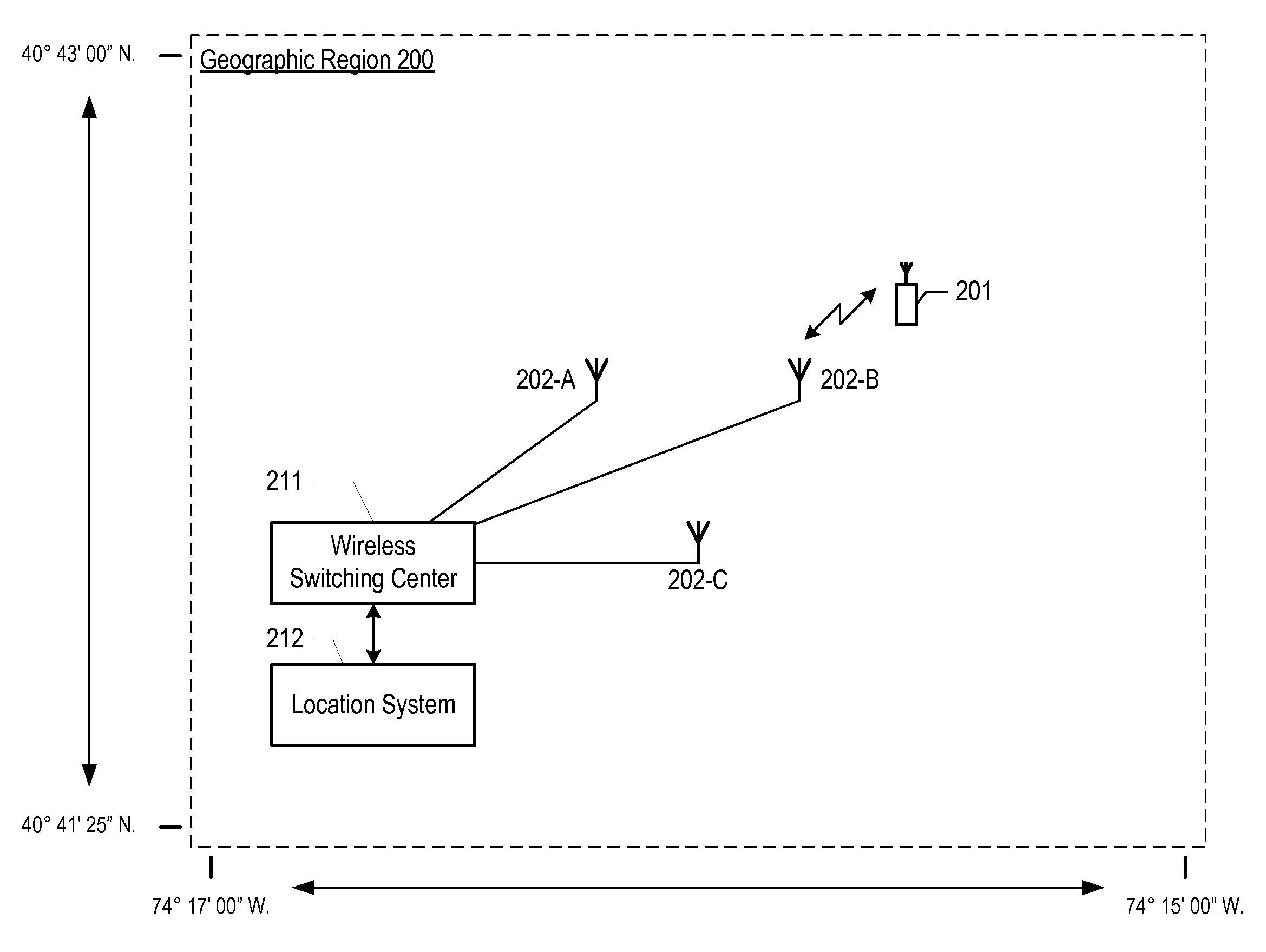
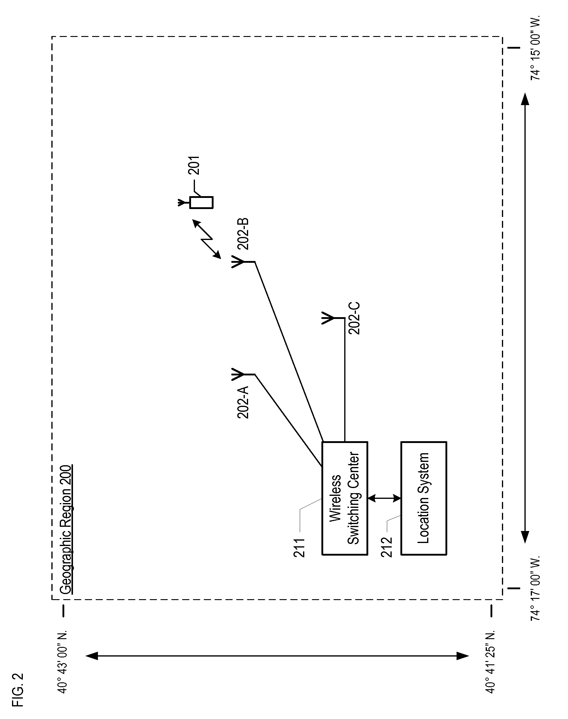
[0040]FIG. 2 depicts a map of the illustrative embodiment of the present invention, which comprises: wireless switching center 211, location system 212, base stations 202-1, 202-2, and 202-3, and wireless terminal 201, which are interconnected as shown. The illustrative embodiment provides wireless telecommunications service to most of geographic region 200, in well-known fashion, and is also capable of estimating the location of wireless terminal 201 within geographic region 200.

[0041]The illustrative embodiment operates in accordance with the Global System for Mobile Communications (formerly known as the Groupe Speciale Mobile), which is ubiquitously known as “GSM.” After reading this disclosure, however, it will be clear to those skilled in the art how to make and use embodiments of the present invention that operate in accordance with other protocols, such as the Universal Mobile Telephone System (“UMTS”), CDMA-2000, and IS-136 TDMA.

[0042]Wireless switching center 211 is a switc...


PUM


Abstract

A method of estimating the location of a wireless terminal is disclosed that is ideally suited for use with legacy systems. The illustrative embodiment of the present invention is based on the observation that the signal strength of a signal from a transmitter is different at some locations, and, therefore, the location of a wireless terminal can be estimated by comparing the signal strength it currently observes against a map or database that correlates locations to signal strengths. For example, if a particular radio station is known to be received well at a first location and poorly at a second location, and a given wireless terminal at an unknown location is receiving the radio station poorly, it is more likely that the wireless terminal is at the second location than it is at the first location.

Description

CROSS-REFERENCE TO RELATED APPLICATION[0001]This application is a continuation of U.S. patent application Ser. No. 10 / 357,645, filed Feb. 4, 2003 (Attorney Docket 465-004us), now pending.[0002]The underlying concepts, but not necessarily the nomenclature, of these applications are incorporated by reference:[0003](i) U.S. Pat. No. 6,269,246, issued 31 Jul. 2001;[0004](ii) U.S. patent application Ser. No. 09 / 532,418, filed 22 Mar. 2000;[0005](iii) U.S. patent application Ser. No. 10 / 128,128, filed 22 Apr. 2002; and[0006](iv) U.S. patent application Ser. No. 10 / 299,398, filed 18 Nov. 2002.FIELD OF THE INVENTION[0007]The present invention relates to telecommunications in general, and, more particularly, to a technique for estimating the location of a wireless terminal.BACKGROUND OF THE INVENTION[0008]FIG. 1 depicts a map of a geographic region that is serviced by a wireless telecommunications system, which system provides wireless telecommunications service to wireless terminals (e.g., ...

Claims


Application Information

Patent Timeline
Patent Type & Authority Applications(United States)
IPC IPC(8): H04Q7/20G01S19/03G01S5/02H04W64/00
CPCG01S5/0252H04W64/00G01S5/02521
Inventor SPAIN, DAVID STEVENSON
Owner POLARIS WIRELESS
Learn More