

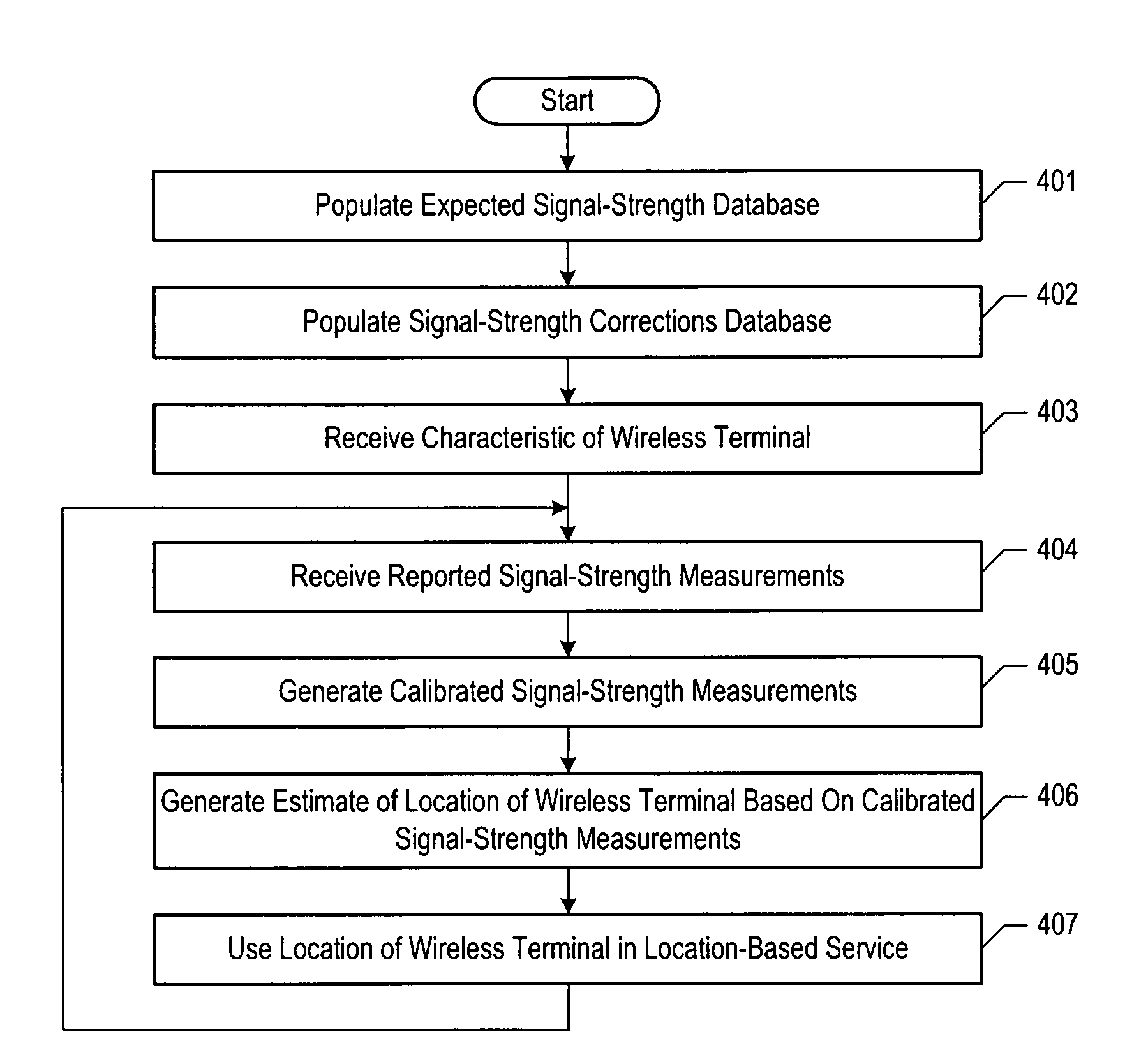
Estimating the location of a wireless terminal based on calibrated signal-strength measurements
a wireless terminal and signal strength technology, applied in the field of telecommunications, can solve the problems of not being able to readily ascertain the location of interested parties, not being able to meet the requirements of higher accuracy, generally not acceptable for applications, emergency services dispatch, etc., and achieves the effect of reducing the number of data points, doubling the variance of random measurement noise, and common bias
- Summary
- Abstract
- Description
- Claims
- Application Information
AI Technical Summary
Benefits of technology
Problems solved by technology
Method used
Image

Examples
Embodiment Construction
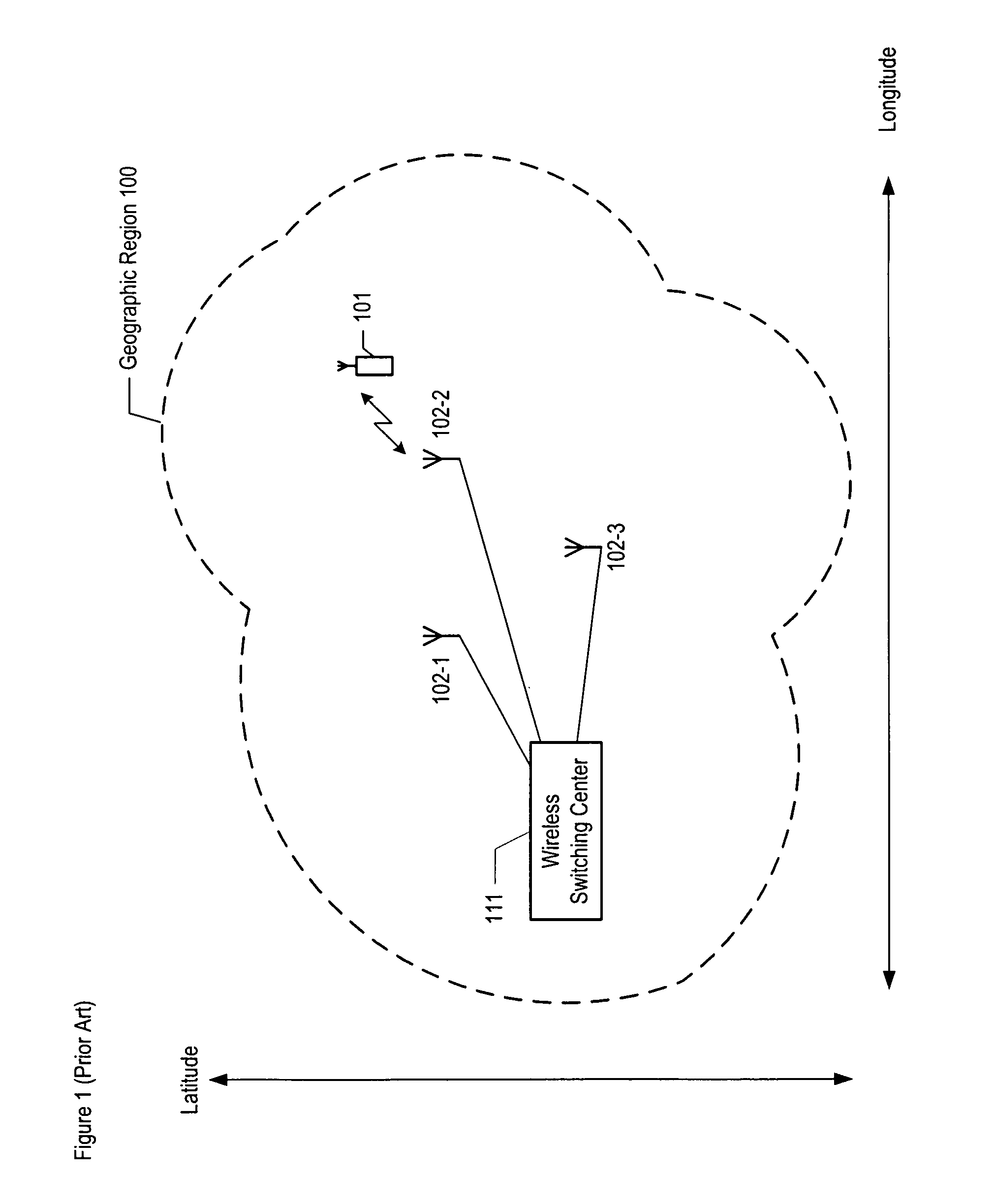
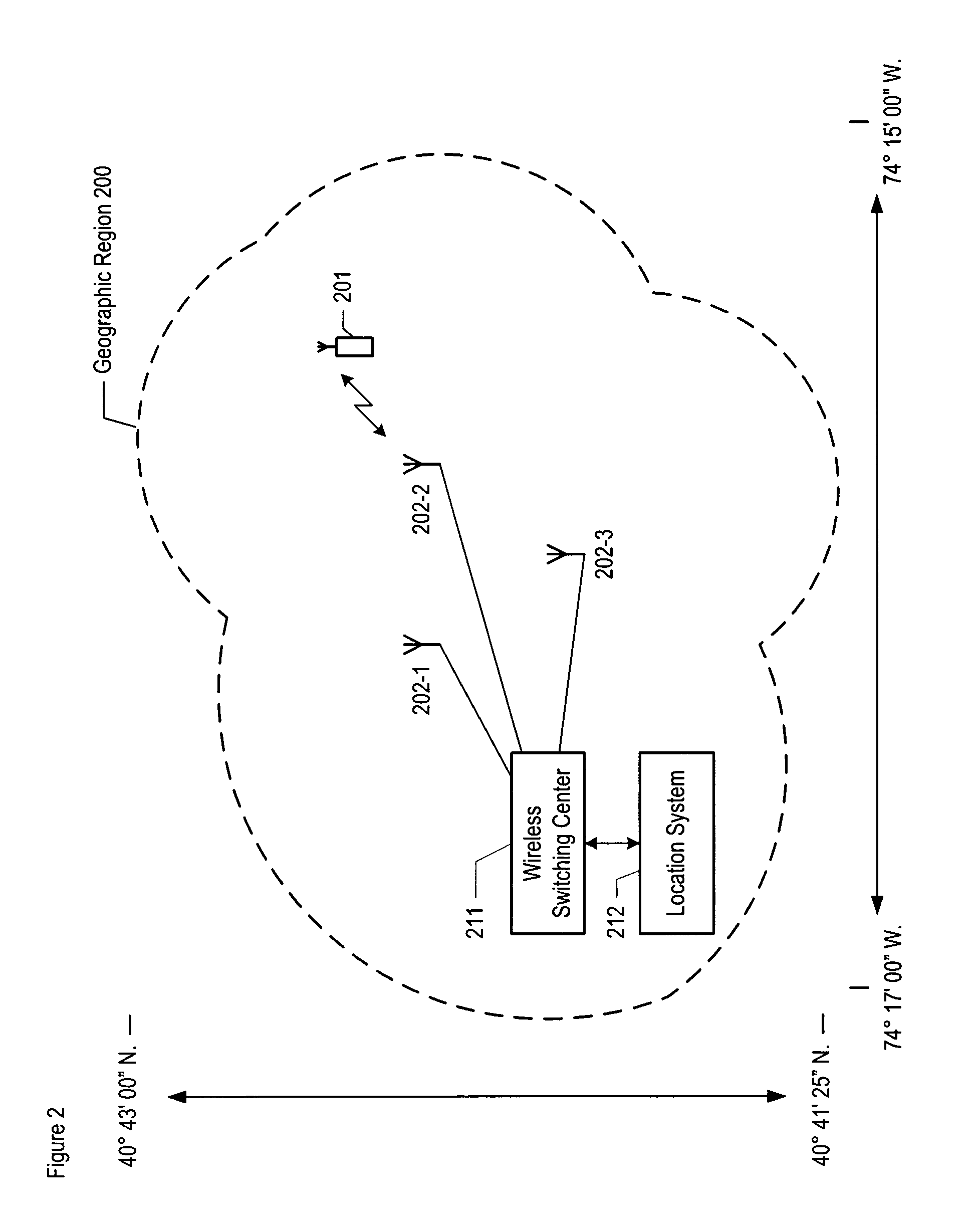
[0054]FIG. 2 depicts a map of the illustrative embodiment of the present invention, which comprises: wireless switching center 211, location system 212, base stations 202-1, 202-2, and 202-3, and wireless terminal 201, which are interconnected as shown. The illustrative embodiment provides wireless telecommunications service to all of geographic region 200, in well-known fashion, and is also capable of estimating the location of wireless terminal 201 within geographic region 200, as described below.
[0055]The illustrative embodiment operates in accordance with the Global System for Mobile Communications (formerly known as the Groupe Speciale Mobile), which is ubiquitously known as “GSM,” and the General Packet Radio Service, which is ubiquitously known as “GPRS.” After reading this disclosure, however, it will be clear to those skilled in the art how to make and use alternative embodiments of the present invention that operate in accordance with other protocols, such as, for example,...
PUM
 Abstract
Description
Claims
Application Information